Prepare the machine and the verification points
The practical route is to move from machine duty to geometry, then to dynamic effects and service conditions, and only then approve a purchase or maintenance action. A tensioner should control slack and vibration, not turn the chain into a highly preloaded member. Placement, force, travel, tooth compatibility, and alignment determine whether the device helps or creates a new load.
Start at the machine, then use the industrial transmission chain options to identify candidates consistent with chain tensioner and idler sprocket. Before a candidate is accepted, use a tensioner only when the layout problem cannot be solved more simply by correct chain length and shaft position. This is deliberately different from choosing a familiar chain number first and trying to make the surrounding drive fit it later.
- Chain Tensioner
- Record this requirement with enough context that a second engineer can reproduce the same selection or diagnosis.
- Idler Sprocket
- Capture this input from a drawing, measurement, calculation, or operating record before the decision advances.
- Slack Span
- Treat this as a controlled variable; note its value, unit, operating state, and source in the job record.
- Wrap Angle
- Verify this item against the physical drive and the current supplier data instead of estimating it from appearance.
- Take-Up Force
- Use this parameter to reject unsuitable options early, then retain the verified value for the final specification.
The tight span already carries the driving load and added deflection there increases forces and articulation. Therefore, confirm the chosen position behaves acceptably in every intended direction of rotation.
Pressing hard on the loaded span can increase bearing reaction and reduce efficiency.
Define the problem the tensioner must solve
A reliable result starts when you decide whether the device compensates for wear, controls a long span, supports a vertical drive, increases wrap, or damps vibration. The underlying reason is different problems call for different idler locations and force characteristics. In service, a spring tensioner used to fix poor sprocket alignment will only hide the root cause. An incorrect input may create adding a tensioner without a defined purpose can increase articulation and bearing loads.
Use the following field evidence: inspect the existing span behavior, wrap, take-up range, and alignment and record the actual symptom. Accept the result only if you can use a tensioner only when the layout problem cannot be solved more simply by correct chain length and shaft position. If the check is visual, add a dimension or operating observation whenever practical.
Place the device on the slack span when possible
Establish the condition by choosing to locate the idler where it controls free chain without carrying the main transmitted tension. It affects the drive because the tight span already carries the driving load and added deflection there increases forces and articulation. A useful constraint is that reversing drives may require a different strategy because tight and slack sides exchange roles. Getting it wrong can produce pressing hard on the loaded span can increase bearing reaction and reduce efficiency.
Confirm the condition this way: draw both torque directions and identify span tension states before choosing the idler side. The step passes when you can confirm the chosen position behaves acceptably in every intended direction of rotation. Keep the evidence beside the chain designation and machine location in the maintenance record.
Preserve or improve small-sprocket wrap
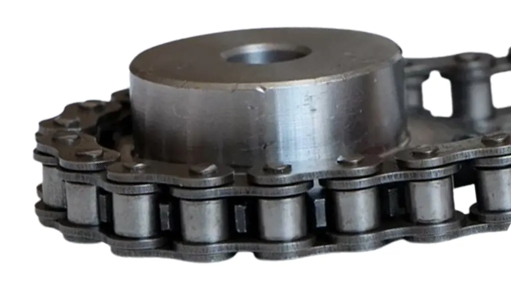
Begin with the physical requirement: position an idler so it does not pull the chain away from the small sprocket or reduce the number of engaged teeth below the required level. It is connected to stable wrap distributes load over more teeth and reduces the risk of jumping. At site level, an idler placed for convenient mounting can unintentionally straighten the chain path and reduce wrap. The avoidable outcome is insufficient engagement can create localized tooth load and unstable entry.
Inspect as follows: sketch or model chain tangency around all sprockets and the idler through its full travel. Release the step after you can verify minimum wrap at both new-chain and worn-chain tensioner positions. Repeat the check after adjustment whenever the adjustment itself can change the measured condition.
Use only enough take-up force to control slack
Select spring, gravity, hydraulic, or fixed adjustment force based on chain mass, orientation, speed, and disturbance rather than applying arbitrary pressure. Why it matters: roller-chain joints and bearings do not benefit from unnecessary pretension. Field nuance: automatic devices can continue increasing force as geometry changes if poorly selected. Failure mode: excess take-up force raises joint, shaft, bearing, and idler loads and can accelerate wear.
Inspection: check tensioner force or spring position over the full travel range and compare with supplier guidance. Release condition: set the device to control the span while the chain still articulates and runs freely. Record the operating state and the reference points used for this check.
Match idler tooth form and alignment
Start by use an idler sprocket compatible with the chain pitch and width, or an approved guide shoe where appropriate, and align it with the chain plane. The mechanism is the idler is another engagement point and can introduce the same mismatch or side-loading problems as a drive sprocket. In practice, multi-strand chains need matching row geometry and a wide flat roller should not ride on an unsuitable narrow guide. If the assumption is wrong, a misaligned idler can create stiff links, edge wear, and periodic lateral steering.
Field check: check pitch, tooth count, face width, bearings, shaft rigidity, and axial position of the idler. Accept the step when you can verify smooth entry and exit with no side contact through the full tensioner travel. Save the measured or observed condition so the result can be repeated later.
Inspect added articulation and lubrication
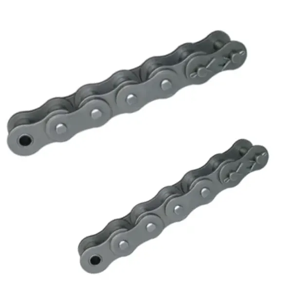
Use consider whether the extra bend around the idler increases joint articulation frequency and whether lubricant reaches that part of the loop. This controls the decision because every additional sprocket or guide changes the chain path and wear distribution. On the machine, a small idler can create severe articulation even though it does not transmit power. The practical risk is using an undersized dry idler can become the highest-wear location in the drive.
Confirm it by doing this: observe link motion around the idler, inspect lubrication film, and compare wear upstream and downstream. The evidence is sufficient when you can increase idler diameter, improve lubrication, or revise placement if the tensioner becomes a concentrated wear point. Note the tool, location, and operating condition with the result.
Procedure verification table
| Decision point | Inspection or calculation | Acceptance evidence |
|---|---|---|
| Define the problem the tensioner must solve | inspect the existing span behavior, wrap, take-up range, and alignment and record the actual symptom | use a tensioner only when the layout problem cannot be solved more simply by correct chain length and shaft position |
| Place the device on the slack span when possible | draw both torque directions and identify span tension states before choosing the idler side | confirm the chosen position behaves acceptably in every intended direction of rotation |
| Preserve or improve small-sprocket wrap | sketch or model chain tangency around all sprockets and the idler through its full travel | verify minimum wrap at both new-chain and worn-chain tensioner positions |
| Use only enough take-up force to control slack | check tensioner force or spring position over the full travel range and compare with supplier guidance | set the device to control the span while the chain still articulates and runs freely |
| Match idler tooth form and alignment | check pitch, tooth count, face width, bearings, shaft rigidity, and axial position of the idler | verify smooth entry and exit with no side contact through the full tensioner travel |
| Inspect added articulation and lubrication | observe link motion around the idler, inspect lubrication film, and compare wear upstream and downstream | increase idler diameter, improve lubrication, or revise placement if the tensioner becomes a concentrated wear point |
| For this article, do not close the job until the chain tensioner evidence and every critical mating interface are recorded together. | ||
Some failures that look like chain problems are controlled by neighboring hardware. review industrial chain tensioner configurations helps illustrate that broader chain tensioner and idler sprocket use context, while the acceptance criteria still come from the actual chain, sprocket, tensioning arrangement, and OEM documentation.
Procedure errors to prevent
Release check: use a tensioner only when the layout problem cannot be solved more simply by correct chain length and shaft position.
Release check: confirm the chosen position behaves acceptably in every intended direction of rotation.
Release check: verify minimum wrap at both new-chain and worn-chain tensioner positions.
Release check: set the device to control the span while the chain still articulates and runs freely.
Procedure FAQs
Finish with a repeatable acceptance check
Release the work only when the record connects chain tensioner and idler sprocket to the physical condition verified in “Inspect added articulation and lubrication.” Include photos or measurements where they clarify the interface, and reference the document that owns any exact limit. The industrial chain drive solutions can then be used to explore alternatives without losing the original engineering basis.
Do not hide a remaining assumption inside the purchase description. send the application data to the chain engineering team with the machine duty, measured interfaces, photographs, and the unresolved question around slack span. A clear uncertainty is actionable; an undocumented guess becomes a future troubleshooting problem.
Send the operating condition, chain tensioner, idler sprocket, layout evidence, and the unresolved interface so the next decision is based on machine data rather than assumption.