Prepare the machine and the verification points
A chain-drive decision becomes much easier when the machine is reduced to measurable inputs instead of being described only as light, medium, or heavy duty. A chain drive is ready for release only when capacity, geometry, interfaces, lubrication, and maintainability agree. This checklist turns those decisions into a sequence that can be reviewed before parts are ordered.
Reviewing the chain product selection range can save time, but only when the search is constrained by verified design power and speed ratio. The engineering gate for this topic is to create one design input sheet with stated units and operating cases; anything that fails that gate remains a hypothesis, not a released specification.
- Design Power
- Treat this as a controlled variable; note its value, unit, operating state, and source in the job record.
- Speed Ratio
- Verify this item against the physical drive and the current supplier data instead of estimating it from appearance.
- Sprocket Selection
- Use this parameter to reject unsuitable options early, then retain the verified value for the final specification.
- Chain Length
- Check this point at the machine and document any uncertainty that still requires a supplier drawing or manual.
- Guarding
- Record this requirement with enough context that a second engineer can reproduce the same selection or diagnosis.
Capture motor, reducer, and driven-machine data: every later chain choice depends on the operating point and load character.
Set ratio and provisional sprocket teeth: small-sprocket tooth count affects chain rating, articulation, polygonal action, and package diameter.
Capture motor, reducer, and driven-machine data
A reliable result starts when you record transmitted power, driver RPM, required driven RPM, driver type, driven machine, starts, reversals, and duty cycle. The underlying reason is every later chain choice depends on the operating point and load character. In service, nameplate power alone does not describe shock, reduction ratio, or actual shaft speed. An incorrect input may create missing duty data forces the selector to guess at service severity.
Use the following field evidence: collect nameplates, controls settings, process throughput, and any torque or current history. Accept the result only if you can create one design input sheet with stated units and operating cases. If the check is visual, add a dimension or operating observation whenever practical.
Convert duty into design power
Establish the condition by choosing to use the selected chain manufacturer service-factor method and rating procedure. It affects the drive because rating tables are based on design conditions that need a defined correction for machine severity. A useful constraint is that adding arbitrary margins or omitting factors makes the calculation hard to audit. Getting it wrong can produce an undocumented safety factor can hide both under-design and needless oversizing.
Confirm the condition this way: show transmitted power, service-factor category, numerical factor, and resulting design power separately. The step passes when you can confirm the correction method and rating table belong to the same chain family. Keep the evidence beside the chain designation and machine location in the maintenance record.
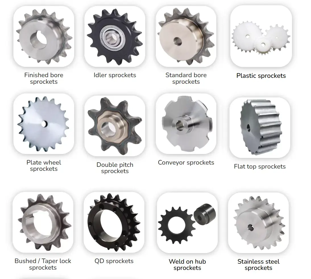
Set ratio and provisional sprocket teeth
Begin with the physical requirement: calculate the required tooth-count ratio and choose a practical small sprocket supported by the rating table. It is connected to small-sprocket tooth count affects chain rating, articulation, polygonal action, and package diameter. At site level, the mathematically smallest sprocket is rarely the best dynamic choice. The avoidable outcome is ratio-only selection can create vibration or an oversized driven sprocket.
Inspect as follows: calculate several integer tooth pairs and compare actual output speed and sprocket diameters. Release the step after you can select a pair that meets ratio tolerance, rating, and machine envelope. Repeat the check after adjustment whenever the adjustment itself can change the measured condition.
Select chain pitch and strand count
Compare rated simplex and multi-strand combinations at the design power and high-speed shaft rpm. Why it matters: pitch and strand count trade radial size, axial width, mass, and smoothness. Field nuance: a larger pitch can make sprockets too large while extra strands increase width and alignment sensitivity. Failure mode: choosing chain size before the sprockets can trap the layout.
Inspection: evaluate candidate chain-and-sprocket combinations together rather than in isolation. Release condition: retain the option that satisfies rating with workable diameters, width, and lubrication. Record the operating state and the reference points used for this check.
Calculate length and design adjustment
Start by calculate whole-link chain length from tooth counts and center distance and place the initial setting within useful take-up travel. The mechanism is real chain is supplied in discrete pitches and will need adjustment during service. In practice, a theoretical center distance can correspond to an impractical link count or end-of-slot installation. If the assumption is wrong, poor adjustment planning increases maintenance and can force offset links or early link removal.
Field check: calculate adjacent link counts and the centers they require, then check the machine slots or tensioner range. Accept the step when you can choose a buildable length with reserve adjustment and adequate small-sprocket wrap. Save the measured or observed condition so the result can be repeated later.
Release interfaces, lubrication, and safety details
Use verify shaft bore, hub, key or locking element, alignment method, guard clearance, lubricant delivery, connecting-link access, and trial-run checks. This controls the decision because a rated chain can still fail if the sprocket is misaligned, poorly lubricated, or impossible to service safely. On the machine, details left for installation crews are often resolved under time pressure. The practical risk is unresolved interfaces can create side wear, dry joints, or unsafe maintenance access.
Confirm it by doing this: review final drawings with manufacturing and maintenance personnel and mark inspection points. The evidence is sufficient when you can issue chain, sprocket, length, mounting, lubrication, alignment, and guard requirements together on the design record. Note the tool, location, and operating condition with the result.
Procedure verification table
| Decision point | Inspection or calculation | Acceptance evidence |
|---|---|---|
| Capture motor, reducer, and driven-machine data | collect nameplates, controls settings, process throughput, and any torque or current history | create one design input sheet with stated units and operating cases |
| Convert duty into design power | show transmitted power, service-factor category, numerical factor, and resulting design power separately | confirm the correction method and rating table belong to the same chain family |
| Set ratio and provisional sprocket teeth | calculate several integer tooth pairs and compare actual output speed and sprocket diameters | select a pair that meets ratio tolerance, rating, and machine envelope |
| Select chain pitch and strand count | evaluate candidate chain-and-sprocket combinations together rather than in isolation | retain the option that satisfies rating with workable diameters, width, and lubrication |
| Calculate length and design adjustment | calculate adjacent link counts and the centers they require, then check the machine slots or tensioner range | choose a buildable length with reserve adjustment and adequate small-sprocket wrap |
| Release interfaces, lubrication, and safety details | review final drawings with manufacturing and maintenance personnel and mark inspection points | issue chain, sprocket, length, mounting, lubrication, alignment, and guard requirements together on the design record |
| For this article, do not close the job until the design power evidence and every critical mating interface are recorded together. | ||
Component selection is strongest when the chain is not reviewed in isolation. review sprocket components used in complete chain drives offers related industrial chain-drive design context; keep the final engineering check tied to the exact standard family, manufacturer table, and measured installation.
Procedure errors to prevent
Release check: create one design input sheet with stated units and operating cases.
Release check: confirm the correction method and rating table belong to the same chain family.
Release check: select a pair that meets ratio tolerance, rating, and machine envelope.
Release check: retain the option that satisfies rating with workable diameters, width, and lubrication.
Procedure FAQs
Finish with a repeatable acceptance check
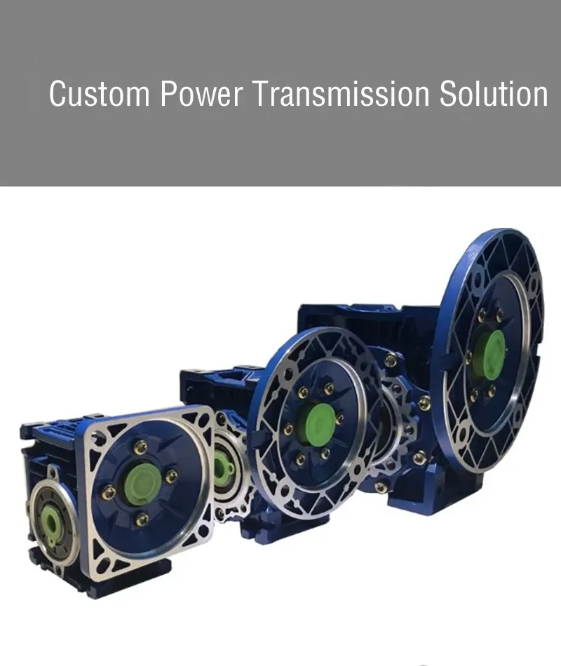
The strongest handoff for this how-to topic is a short evidence package: verified design power, verified speed ratio, the result of “Release interfaces, lubrication, and safety details,” and the exact source of any chain-series-specific limit. Broader alternatives on the power transmission chain solutions should be compared against that same package rather than against generic catalog descriptions.
For industrial chain-drive design, if sprocket selection has not been verified, send the application data to the chain engineering team with the evidence collected in the preceding checks. State the operating condition, measured dimensions, current sprocket condition, and intended maintenance or design action so the remaining check can be closed before the machine returns to service.
Send the operating condition, design power, speed ratio, layout evidence, and the unresolved interface so the next decision is based on machine data rather than assumption.