Define the interfaces that must match
For an industrial drive, the useful question is not whether a chain looks strong enough; it is whether the selected chain, sprockets, lubrication, and layout work together under the real duty. A chain that can be laid over a sprocket is not automatically compatible. Correct engagement requires the chain dimensions and sprocket tooth geometry to belong to the same system and the sprocket must also fit the shaft and alignment envelope.
The available transmission chain families is most useful once the problem statement includes chain pitch and tooth profile. In this article the controlling verification is to confirm both components are intended for the same nominal pitch and standard family. Keeping those facts together gives purchasing and maintenance the same technical basis for the next action.
- Chain Pitch
- Use this parameter to reject unsuitable options early, then retain the verified value for the final specification.
- Tooth Profile
- Check this point at the machine and document any uncertainty that still requires a supplier drawing or manual.
- Sprocket Face Width
- Record this requirement with enough context that a second engineer can reproduce the same selection or diagnosis.
- Strand Count
- Capture this input from a drawing, measurement, calculation, or operating record before the decision advances.
- Roller Diameter
- Treat this as a controlled variable; note its value, unit, operating state, and source in the job record.
Confirm pitch from controlled dimensions
A reliable result starts when you verify chain pitch from the part drawing or a multi-link measurement and compare it with the sprocket designation. The underlying reason is pitch is the first compatibility gate because every tooth-to-roller spacing depends on it. In service, worn chains have elongated joint clearances, so single-pitch measurements can be misleading. An incorrect input may create a wrong pitch can ride up, bind, or impact tooth flanks instead of seating normally.
Use the following field evidence: measure several pitches under light tension and count sprocket teeth and designation markings. Accept the result only if you can confirm both components are intended for the same nominal pitch and standard family. If the check is visual, add a dimension or operating observation whenever practical.
Match roller diameter to tooth seating
Establish the condition by choosing to compare roller outside diameter with the sprocket tooth-space profile for the selected chain series. It affects the drive because the roller must enter and leave the tooth pocket along the intended contact path. A useful constraint is that chains from different families can share pitch but use different roller geometry. Getting it wrong can produce an oversized or undersized roller can change seating depth and contact location.
Confirm the condition this way: measure several intact rollers and inspect tooth-pocket clearance with the supplier drawings. The step passes when you can verify the sprocket tooth section is specified for that chain roller diameter. Keep the evidence beside the chain designation and machine location in the maintenance record.
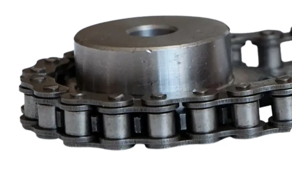
Check inner width and sprocket tooth thickness
Begin with the physical requirement: compare the chain width between inner plates with the sprocket tooth or plate thickness and required side clearance. It is connected to the chain needs enough lateral clearance to articulate without excessive side movement. At site level, corrosion, burrs, or paint can make a sprocket effectively wider than its drawing. The avoidable outcome is too little clearance causes binding while excessive or mismatched width can reduce guidance.
Inspect as follows: measure inner width and sprocket tooth thickness at unworn locations and inspect for burrs. Release the step after you can confirm side clearance falls within the chain and sprocket manufacturer dimensional system. Repeat the check after adjustment whenever the adjustment itself can change the measured condition.
Match strand count and transverse pitch
Verify simplex, duplex, triplex, or wider chain rows against the same number and spacing of sprocket tooth rows. Why it matters: multi-strand chain acts as one assembly and depends on row-to-row alignment. Field nuance: two simplex sprockets mounted separately are not automatically equivalent to one duplex sprocket. Failure mode: incorrect transverse spacing creates unequal row loading and side stress.
Inspection: measure center spacing between tooth rows and compare with chain transverse pitch and overall width. Release condition: use a matched multi-strand sprocket or an engineered assembly with documented geometry. Record the operating state and the reference points used for this check.
Verify standard and tooth-form family
Start by check whether the chain and sprocket follow the same ASME/ANSI, ISO/BS, double-pitch, silent-chain, or specialty standard. The mechanism is different chain types use different engagement and tooth geometry even when nominal pitch seems familiar. In practice, silent chains, double-pitch chains, and specialty bush chains are especially easy to misidentify visually. If the assumption is wrong, mixing standards can produce contact problems that are not obvious while stationary.
Field check: review part numbers, supplier drawings, and standard references for both components. Accept the step when you can state the chain series and compatible sprocket designation on the installation record. Save the measured or observed condition so the result can be repeated later.
Check the shaft and installed alignment too
Use verify bore, key or locking element, hub face, runout, axial position, and shaft parallelism before fitting the chain. This controls the decision because a geometrically compatible sprocket can still damage the chain if mounted eccentrically or out of plane. On the machine, shaft shoulders and bushings may shift the tooth row from the intended centerline. The practical risk is compatibility without installation alignment still produces side wear and cyclic tension.
Confirm it by doing this: dry-fit sprockets, secure them, then measure runout and tooth-row alignment across the span. The evidence is sufficient when you can install the chain only after both component geometry and mounted position are confirmed. Note the tool, location, and operating condition with the result.
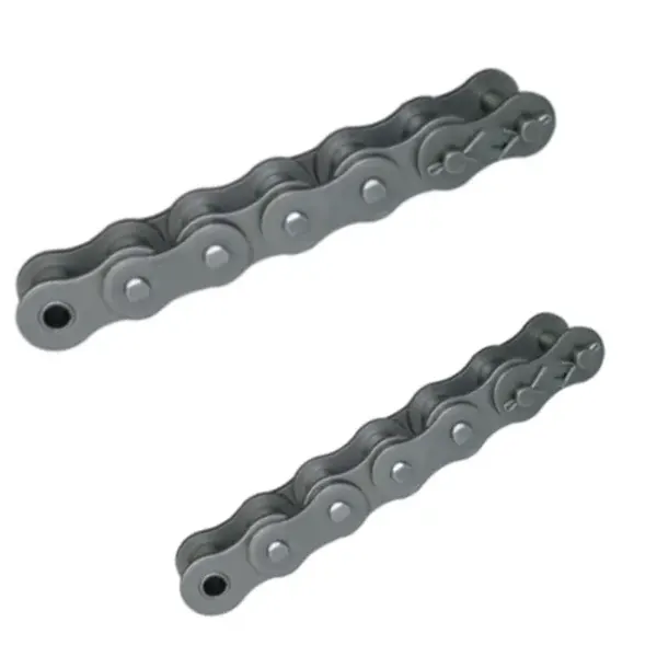
Compatibility verification table
| Decision point | Inspection or calculation | Acceptance evidence |
|---|---|---|
| Confirm pitch from controlled dimensions | measure several pitches under light tension and count sprocket teeth and designation markings | confirm both components are intended for the same nominal pitch and standard family |
| Match roller diameter to tooth seating | measure several intact rollers and inspect tooth-pocket clearance with the supplier drawings | verify the sprocket tooth section is specified for that chain roller diameter |
| Check inner width and sprocket tooth thickness | measure inner width and sprocket tooth thickness at unworn locations and inspect for burrs | confirm side clearance falls within the chain and sprocket manufacturer dimensional system |
| Match strand count and transverse pitch | measure center spacing between tooth rows and compare with chain transverse pitch and overall width | use a matched multi-strand sprocket or an engineered assembly with documented geometry |
| Verify standard and tooth-form family | review part numbers, supplier drawings, and standard references for both components | state the chain series and compatible sprocket designation on the installation record |
| Check the shaft and installed alignment too | dry-fit sprockets, secure them, then measure runout and tooth-row alignment across the span | install the chain only after both component geometry and mounted position are confirmed |
| For this article, do not close the job until the chain pitch evidence and every critical mating interface are recorded together. | ||
For a wider view of the hardware around this problem, see review chain sprocket geometry and standards. Use that page only as context for sprocket and roller-chain compatibility; approve the real drive from measured interfaces, current ratings, and the machine duty described in this article.
Mismatch risks to eliminate
Release check: confirm both components are intended for the same nominal pitch and standard family.
Release check: verify the sprocket tooth section is specified for that chain roller diameter.
Release check: confirm side clearance falls within the chain and sprocket manufacturer dimensional system.
Release check: use a matched multi-strand sprocket or an engineered assembly with documented geometry.
Compatibility FAQs
Approve interchangeability only after every interface matches
A finished compatibility decision should let another engineer reproduce it without relying on memory. Keep chain pitch, tooth profile, the final check for “Check the shaft and installed alignment too,” and the governing catalog or drawing revision together. If another chain architecture becomes relevant, the chain drive engineering solutions is a starting point, not a replacement for those recorded inputs.
For an application-specific review, send the application data to the chain engineering team and identify what is known versus what remains uncertain. Include the values for chain pitch and tooth profile, plus the current condition of sprocket face width. A supplier can then evaluate a bounded engineering question instead of trying to infer the machine from a chain designation alone.
Send the operating condition, chain pitch, tooth profile, layout evidence, and the unresolved interface so the next decision is based on machine data rather than assumption.