Prepare the machine and the verification points
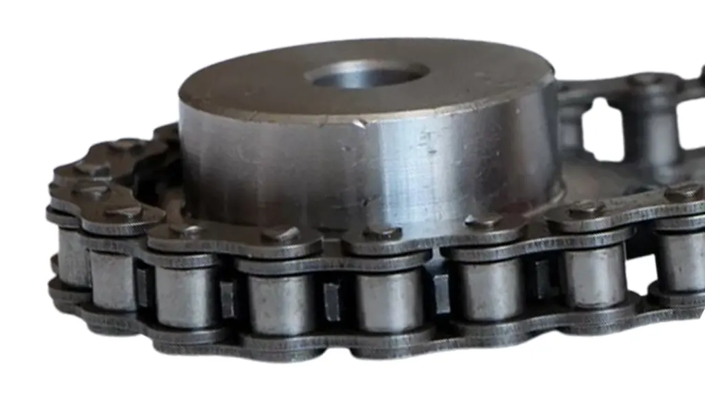
For an industrial drive, the useful question is not whether a chain looks strong enough; it is whether the selected chain, sprockets, lubrication, and layout work together under the real duty. Sprocket alignment is a two-part problem: the shaft axes must be parallel, and the sprocket tooth rows must share the same plane. Runout can make a drive appear aligned at one angular position and misaligned half a revolution later.
A practical way to use the roller and transmission chain range is to narrow the product family after the machine has supplied evidence for shaft parallelism and axial alignment. The selected option should then survive this check: confirm the chosen surfaces are concentric or parallel with the actual tooth row. If it does not, return to the duty or geometry rather than adding an arbitrary safety margin.
- Shaft Parallelism
- Use this parameter to reject unsuitable options early, then retain the verified value for the final specification.
- Axial Alignment
- Check this point at the machine and document any uncertainty that still requires a supplier drawing or manual.
- Sprocket Runout
- Record this requirement with enough context that a second engineer can reproduce the same selection or diagnosis.
- Tooth Row
- Capture this input from a drawing, measurement, calculation, or operating record before the decision advances.
- Side Wear
- Treat this as a controlled variable; note its value, unit, operating state, and source in the job record.
Alignment readings are only meaningful when taken from stable datums and the drive cannot move unexpectedly. The practical release check is to confirm the chosen surfaces are concentric or parallel with the actual tooth row.

Lock out the drive and choose valid datums
Work from isolate the machine, remove load from the chain where necessary, and identify shaft or sprocket surfaces that are machined and suitable for measurement. The engineering link is alignment readings are only meaningful when taken from stable datums and the drive cannot move unexpectedly. One useful detail is that painted hub faces, damaged guards, or rough cast surfaces can mislead a straightedge check. Otherwise, measuring from the wrong surfaces can produce a precise but incorrect alignment.
Verify at the drive: clean shaft shoulders and sprocket faces, verify bearing security, and mark the intended measurement datums. Close this check only after you can confirm the chosen surfaces are concentric or parallel with the actual tooth row. Keep photographs or dimensions when they help preserve the interface condition.
Correct shaft angular error first
Base the decision on measure whether the driver and driven shaft axes are parallel in the horizontal and vertical planes. It matters because axial sprocket shifting cannot compensate for shafts that point in different directions. During service, longer center distances make small angular errors easier to see as lateral chain displacement. A poor assumption can cause leaving angular error forces each joint to correct sideways as it travels between sprockets.
Use this confirmation: use a laser, straightedge geometry, or other machine alignment method referenced to the shaft axes and bearing locations. Proceed when you can bring both shaft axes within the machine or component alignment tolerance before setting sprocket position. If readings vary around the chain or sprocket, retain the spread instead of hiding it in one average.
Set the tooth rows in one plane
The controlling action is to move sprockets axially on their shafts until the corresponding tooth rows align across the span. Its significance comes from the chain should approach each sprocket without side force on the inner or outer link plates. In the field, multi-strand sprockets require every tooth row to align, not only the outer faces. The failure consequence is axial offset produces polished side faces, uneven roller marks, and edge wear on sprocket teeth.
Check the hardware directly: place a straightedge or laser across suitable sprocket datum faces and correct for known face offsets between different sprocket designs. Approval requires that you can verify the chain centerline matches both sprockets and remains clear of guides and guards. Write down any uncertainty that still needs a drawing, manual, or supplier response.
Measure radial and face runout
First, rotate each sprocket slowly and observe changes in radial position and face alignment at several angular locations. That step is tied to bore eccentricity, bent shafts, dirt under a hub, or poor mounting can move the tooth row cyclically. A practical observation is that an alignment check at one angular position can miss a high spot that tightens the chain once per revolution. Missing it can lead to runout creates cyclic tension, noise, and alternating side contact that accelerates wear.
For evidence, use a dial indicator on appropriate machined surfaces or a repeatable fixed pointer and record maximum variation through one rotation. Finish when you can compare runout with the sprocket and machine specification and correct mounting or damaged components as needed. Retain enough context to distinguish a new-chain dimension from a wear-affected measurement.
Tighten hubs without losing alignment
Treat secure keys, bushings, locking elements, set screws, or fasteners in the specified sequence and remeasure afterward as the control point. The reason is clamping can pull a sprocket against a shoulder or taper and change both axial position and runout. Real installations also show that a clean dry taper may seat differently from a contaminated one and over-tightening can distort components. The likely consequence of error is assuming alignment survives tightening can leave the final drive outside tolerance.
Make the check at the machine: mark the aligned position, tighten using the manufacturer method, then repeat parallelism, axial, and runout measurements. The release criterion is to release the chain installation only after the secured sprockets reproduce the alignment readings. Record whether the drive was stopped, loaded, warm, cold, clean, or contaminated as relevant.
Use wear patterns as a final feedback check
Do not choose the hardware until you inspect side plates, roller tracks, and sprocket tooth flanks after a controlled run. This matters because contact patterns reveal alignment errors under actual load that static measurement may miss. Remember that uniform polish near the intended seating region differs from one-sided bright wear or scuffing. If ignored, ignoring asymmetric wear allows a small alignment error to become a large maintenance problem.
Validate with a repeatable observation: run the drive at low load, stop safely, and compare left-right contact marks on both sprockets and chain plates. Move on after you can re-align if wear or tracking is consistently biased to one side. Preserve the source of any numerical limit that belongs to a specific chain series.
Procedure verification table
| Decision point | Inspection or calculation | Acceptance evidence |
|---|---|---|
| Lock out the drive and choose valid datums | clean shaft shoulders and sprocket faces, verify bearing security, and mark the intended measurement datums | confirm the chosen surfaces are concentric or parallel with the actual tooth row |
| Correct shaft angular error first | use a laser, straightedge geometry, or other machine alignment method referenced to the shaft axes and bearing locations | bring both shaft axes within the machine or component alignment tolerance before setting sprocket position |
| Set the tooth rows in one plane | place a straightedge or laser across suitable sprocket datum faces and correct for known face offsets between different sprocket designs | verify the chain centerline matches both sprockets and remains clear of guides and guards |
| Measure radial and face runout | use a dial indicator on appropriate machined surfaces or a repeatable fixed pointer and record maximum variation through one rotation | compare runout with the sprocket and machine specification and correct mounting or damaged components as needed |
| Tighten hubs without losing alignment | mark the aligned position, tighten using the manufacturer method, then repeat parallelism, axial, and runout measurements | release the chain installation only after the secured sprockets reproduce the alignment readings |
| Use wear patterns as a final feedback check | run the drive at low load, stop safely, and compare left-right contact marks on both sprockets and chain plates | re-align if wear or tracking is consistently biased to one side |
| For this article, do not close the job until the shaft parallelism evidence and every critical mating interface are recorded together. | ||
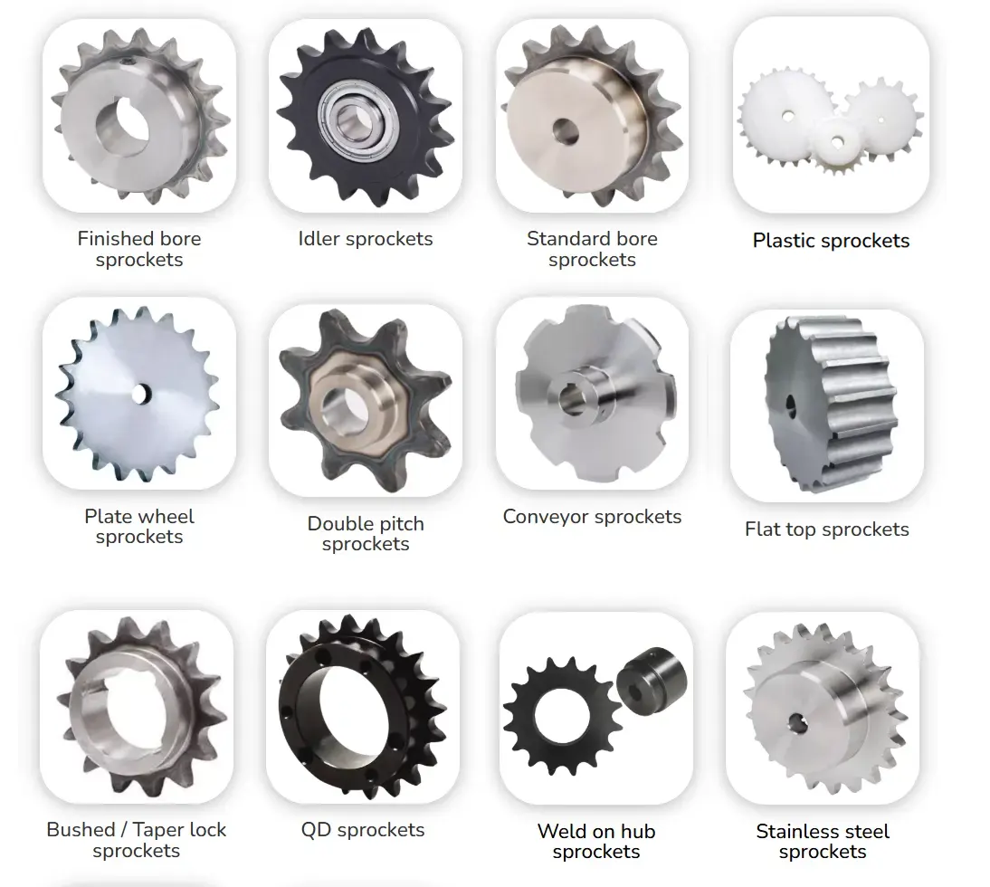
When the decision extends beyond the chain itself, review sprocket geometry and hub arrangements is a useful adjacent-hardware reference for chain-sprocket alignment. It is not a substitute for checking tooth geometry, mounting, capacity, and the selected chain standard on the final drawing.
Procedure errors to prevent
Release check: confirm the chosen surfaces are concentric or parallel with the actual tooth row.
Release check: bring both shaft axes within the machine or component alignment tolerance before setting sprocket position.
Release check: verify the chain centerline matches both sprockets and remains clear of guides and guards.
Release check: compare runout with the sprocket and machine specification and correct mounting or damaged components as needed.
Procedure FAQs
Finish with a repeatable acceptance check
The output should be more useful than a part number. Record shaft parallelism, axial alignment, the condition found during “Use wear patterns as a final feedback check,” and the evidence used to accept or reject the change. That makes the decision auditable after the next shutdown. Use the industrial drive-chain capabilities to compare other transmission-chain families only when the same duty data is carried forward.
Where the final answer still depends on missing machine data, send the application data to the chain engineering team. Include the duty, speed, geometry and inspection evidence that led to the current conclusion, with sprocket runout called out separately. The goal is to obtain a drawing-level answer before hardware is ordered or an adjustment becomes the new baseline.
Send the operating condition, shaft parallelism, axial alignment, layout evidence, and the unresolved interface so the next decision is based on machine data rather than assumption.