Prepare for a controlled installation
Most costly chain-drive mistakes begin when one visible symptom or one catalog dimension is treated as the whole problem. The connecting link closes the load path and deserves the same care as the rest of the chain. Link style, plate fit, retainer orientation, and articulation vary by chain series, so the exact manufacturer instructions control the assembly.
A practical way to use the roller and transmission chain range is to narrow the product family after the machine has supplied evidence for connecting link and spring clip. The selected option should then survive this check: use only the connecting link specified for the installed chain series. If it does not, return to the duty or geometry rather than adding an arbitrary safety margin.
Connecting links that share nominal pitch can differ in pin length, plate fit, retainer, or strength. The practical release check is to use only the connecting link specified for the installed chain series.
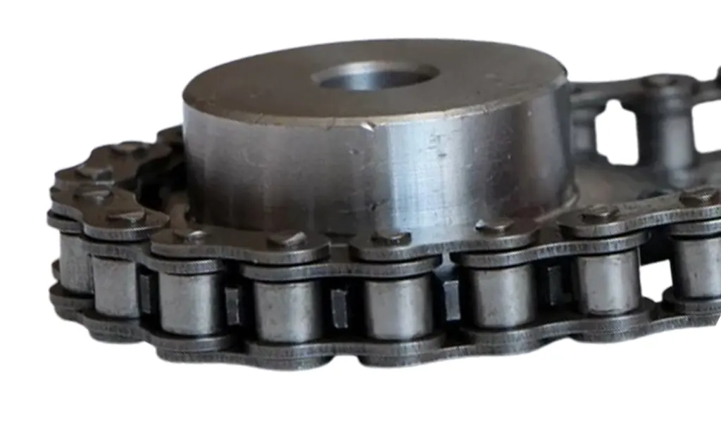
- Connecting Link
- Verify this item against the physical drive and the current supplier data instead of estimating it from appearance.
- Spring Clip
- Use this parameter to reject unsuitable options early, then retain the verified value for the final specification.
- Cotter Pin
- Check this point at the machine and document any uncertainty that still requires a supplier drawing or manual.
- Press Fit
- Record this requirement with enough context that a second engineer can reproduce the same selection or diagnosis.
- Link Plate
- Capture this input from a drawing, measurement, calculation, or operating record before the decision advances.
Identify the exact connecting-link type
First, match the link to chain number, strand count, series, and manufacturer construction before opening the package. That step is tied to connecting links that share nominal pitch can differ in pin length, plate fit, retainer, or strength. A practical observation is that heavy-duty and specialty chains may use different joining hardware from standard roller chain. Missing it can lead to using a near-match link can create loose plates, binding, or reduced strength.
For evidence, compare markings and dimensions on the link with the chain and supplier drawing. Finish when you can use only the connecting link specified for the installed chain series. Retain enough context to distinguish a new-chain dimension from a wear-affected measurement.
Prepare the chain ends without damaging plates or pins
Treat bring the two chain ends together on the sprocket or a supported straight section and ensure the end links are clean, aligned, and undistorted as the control point. The reason is forced alignment can bend plates or side-load pins before the link is installed. Real installations also show that dirty joint faces can interfere with plate seating and lubricant access. The likely consequence of error is hammering or prying the chain ends together can create hidden assembly damage.
Make the check at the machine: support the chain, remove burrs or contamination, and align the end holes without twisting the strand. The release criterion is to confirm both ends articulate normally and meet without force before inserting the link pins. Record whether the drive was stopped, loaded, warm, cold, clean, or contaminated as relevant.
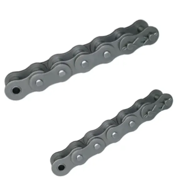
Seat the connecting plate using the specified fit
Do not choose the hardware until you press or slide the outer plate onto the pins using the approved tool and target position for that link design. This matters because some plates are slip fit while others require controlled press fit to provide the intended retention. Remember that driving a plate with a hammer can distort holes, peen pin ends, or jam the joint. If ignored, incorrect plate position can leave excessive side clearance or bind the adjacent link.
Validate with a repeatable observation: measure or visually compare plate position with neighboring links and use a chain tool where specified. Move on after you can verify the plate is fully seated, parallel, and undamaged without squeezing the joint. Preserve the source of any numerical limit that belongs to a specific chain series.
Install the retainer in the correct orientation
A reliable result starts when you fit the spring clip, cotter, or other retainer exactly as specified and ensure it is fully engaged. The underlying reason is the retainer prevents the connecting plate from leaving the pins during service. In service, clip orientation can matter where objects or chain travel could catch the open end. An incorrect input may create a partially seated clip or wrong cotter can be lost and allow plate separation.
Use the following field evidence: inspect groove engagement, clip direction, cotter spread, and clearance from guards or guides. Accept the result only if you can confirm the retainer is secure and cannot contact stationary structure through a full revolution. If the check is visual, add a dimension or operating observation whenever practical.
Lubricate the new joint
Establish the condition by choosing to apply the correct lubricant so it reaches the pin-bushing or pin-link interfaces of the connecting link. It affects the drive because assembly handling can remove factory lubricant and the connecting joint must articulate immediately under load. A useful constraint is that oil on the outside plate does not guarantee the pin surface is protected. Getting it wrong can produce a dry connecting link can develop fretting or stiffness earlier than neighboring factory joints.
Confirm the condition this way: work lubricant into the joint at the plate gaps and compare movement with adjacent links. The step passes when you can verify a clean lubricant film and free articulation before closing the guard. Keep the evidence beside the chain designation and machine location in the maintenance record.
Inspect the link during trial operation
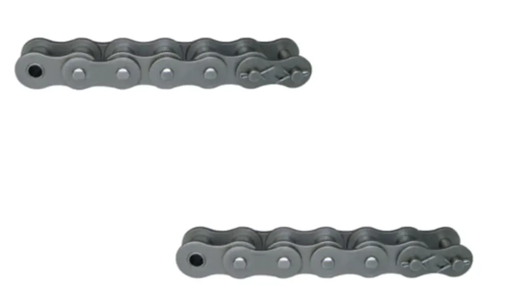
Begin with the physical requirement: rotate the drive slowly, then run under controlled conditions while watching the connecting link pass both sprockets. It is connected to a wrongly seated plate or stiff joint often becomes visible as it articulates through a sprocket. At site level, the joint may appear free in a straight span but bind under wrap. The avoidable outcome is full-speed commissioning can turn a small assembly error into plate or sprocket damage.
Inspect as follows: mark the connecting link and observe tracking, plate clearance, noise, and articulation for several cycles. Release the step after you can stop and correct any binding, plate movement, or retainer contact before normal production. Repeat the check after adjustment whenever the adjustment itself can change the measured condition.
Installation acceptance table
| Decision point | Inspection or calculation | Acceptance evidence |
|---|---|---|
| Identify the exact connecting-link type | compare markings and dimensions on the link with the chain and supplier drawing | use only the connecting link specified for the installed chain series |
| Prepare the chain ends without damaging plates or pins | support the chain, remove burrs or contamination, and align the end holes without twisting the strand | confirm both ends articulate normally and meet without force before inserting the link pins |
| Seat the connecting plate using the specified fit | measure or visually compare plate position with neighboring links and use a chain tool where specified | verify the plate is fully seated, parallel, and undamaged without squeezing the joint |
| Install the retainer in the correct orientation | inspect groove engagement, clip direction, cotter spread, and clearance from guards or guides | confirm the retainer is secure and cannot contact stationary structure through a full revolution |
| Lubricate the new joint | work lubricant into the joint at the plate gaps and compare movement with adjacent links | verify a clean lubricant film and free articulation before closing the guard |
| Inspect the link during trial operation | mark the connecting link and observe tracking, plate clearance, noise, and articulation for several cycles | stop and correct any binding, plate movement, or retainer contact before normal production |
| For this article, do not close the job until the connecting link evidence and every critical mating interface are recorded together. | ||
When the decision extends beyond the chain itself, review roller-chain joining and size context is a useful adjacent-hardware reference for roller-chain connecting-link installation. It is not a substitute for checking tooth geometry, mounting, capacity, and the selected chain standard on the final drawing.
Installation faults to eliminate
Release check: use only the connecting link specified for the installed chain series.
Release check: confirm both ends articulate normally and meet without force before inserting the link pins.
Release check: verify the plate is fully seated, parallel, and undamaged without squeezing the joint.
Release check: confirm the retainer is secure and cannot contact stationary structure through a full revolution.
Installation FAQs
Commission the drive from a known baseline
The output should be more useful than a part number. Record connecting link, spring clip, the condition found during “Inspect the link during trial operation,” and the evidence used to accept or reject the change. That makes the decision auditable after the next shutdown. Use the industrial drive-chain capabilities to compare other transmission-chain families only when the same duty data is carried forward.
Where the final answer still depends on missing machine data, send the application data to the chain engineering team. Include the duty, speed, geometry and inspection evidence that led to the current conclusion, with cotter pin called out separately. The goal is to obtain a drawing-level answer before hardware is ordered or an adjustment becomes the new baseline.
Send the operating condition, connecting link, spring clip, layout evidence, and the unresolved interface so the next decision is based on machine data rather than assumption.