Prepare for a controlled installation
Most costly chain-drive mistakes begin when one visible symptom or one catalog dimension is treated as the whole problem. Premature wear often starts at installation. A new chain cannot compensate for skewed shafts, hooked sprockets, a tight span, a dry joint, or an incorrectly assembled connecting link.
Use the transmission chain product range as a map of available chain families only after you have captured shaft alignment and sprocket alignment. For this topic, the first release condition is specific: confirm both sprockets match the chain series and are free of defects that affect engagement. That sequence keeps catalog browsing from turning into a pitch-only or appearance-only substitution.
- Shaft Alignment
- Verify this item against the physical drive and the current supplier data instead of estimating it from appearance.
- Sprocket Alignment
- Use this parameter to reject unsuitable options early, then retain the verified value for the final specification.
- Connecting Link
- Check this point at the machine and document any uncertainty that still requires a supplier drawing or manual.
- Chain Slack
- Record this requirement with enough context that a second engineer can reproduce the same selection or diagnosis.
- Trial Run
- Capture this input from a drawing, measurement, calculation, or operating record before the decision advances.
Inspect the chain and sprockets before assembly
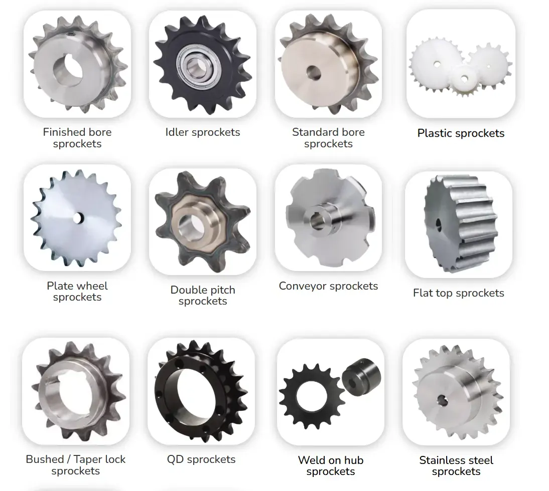
Check the new chain for shipping damage and verify sprocket tooth condition, bore, hub, keyway, and chain compatibility. Why it matters: installation quality begins with known-good components and a new chain should not be placed on a visibly damaged interface. Field nuance: sprocket hooking, burrs, corrosion, or incorrect tooth form can damage a new chain from the first rotation. Failure mode: fitting parts without incoming inspection can turn a parts problem into an installation problem.
Inspection: compare chain and sprocket part numbers with the drawing and inspect teeth, rollers, pins, plates, bore, and mounting surfaces. Release condition: confirm both sprockets match the chain series and are free of defects that affect engagement. Record the operating state and the reference points used for this check.
Make the shafts parallel before aligning sprockets
Start by level or reference the shafts and correct angular misalignment at the bearing or machine mount. The mechanism is a straight chain span cannot run correctly when the shaft axes are not parallel. In practice, adjusting sprocket axial position alone cannot correct angular shaft error. If the assumption is wrong, nonparallel shafts force the chain sideways and create uneven plate and tooth contact.
Field check: measure shaft parallelism with suitable straightedge, level, laser, or machine alignment method across the supported shaft length. Accept the step when you can bring shaft alignment within the machine and chain manufacturer requirement before mounting the chain. Save the measured or observed condition so the result can be repeated later.
Align sprocket faces or datum planes axially
Use position the sprockets so their chain tooth rows lie in the same plane and secure the hubs without introducing runout. This controls the decision because roller chain has limited tolerance for side loading and should enter each sprocket without lateral correction. On the machine, hub faces are not always a valid alignment datum if sprockets have different hub designs. The practical risk is axial offset creates side wear on plates and tooth flanks and can push the chain toward a guard.
Confirm it by doing this: use a straightedge, string, or laser across known sprocket datum faces and rotate the shafts to check runout effects. The evidence is sufficient when you can confirm the tooth rows remain aligned through a full rotation before installing the chain. Note the tool, location, and operating condition with the result.
Install the strand without forcing it tight
Work from fit the calculated link count with the take-up in its planned initial position and join the chain without prying it over sprocket teeth. The engineering link is chain drives need controlled slack and do not use belt-like pretension. One useful detail is that forcing a short chain can overload bearings and strip lubricant from joints. Otherwise, excessive initial tension accelerates joint and bearing wear while a very loose chain can whip or climb teeth.
Verify at the drive: rotate the unloaded drive by hand or inching mode and observe upper and lower span behavior over one full loop. Close this check only after you can set slack using the selected manufacturer guidance for orientation, span, load, and speed. Keep photographs or dimensions when they help preserve the interface condition.
Assemble the connecting link exactly as specified
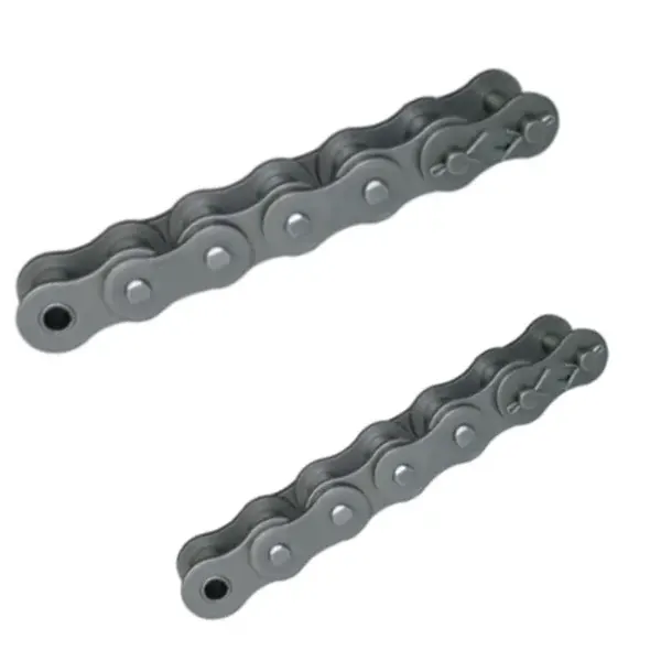
Base the decision on install the connecting plate, clip, cotter, or riveted connection in the correct orientation with the approved tool and fit. It matters because the connecting link is part of the load path and improper plate fit can reduce reliability. During service, clip-type links can be directional in relation to chain travel and press-fit plates can be damaged by hammering. A poor assumption can cause a loose plate, missing retainer, or distorted pin can become an early failure site.
Use this confirmation: inspect the link after assembly for full plate seating, retainer engagement, free articulation, and absence of plate damage. Proceed when you can confirm the connection matches the chain manufacturer assembly instructions and moves as freely as neighboring links. If readings vary around the chain or sprocket, retain the spread instead of hiding it in one average.
Lubricate and trial-run before full production
The controlling action is to ensure lubricant reaches pin-bushing joints, install guards, then run first at low or no process load while listening and observing. Its significance comes from a trial run reveals contact, vibration, tracking, and stiff-link problems before they are amplified by full load. In the field, new components can seat slightly and the initial slack may change after the first operating period. The failure consequence is skipping the trial run can allow a minor alignment or clearance problem to damage the whole strand.
Check the hardware directly: check noise, vibration, guard clearance, chain tracking, sprocket engagement, lubrication, temperature, and connecting-link condition during and after the trial. Approval requires that you can recheck alignment and slack after initial operation and correct any abnormal condition before production release. Write down any uncertainty that still needs a drawing, manual, or supplier response.
Installation acceptance table
| Decision point | Inspection or calculation | Acceptance evidence |
|---|---|---|
| Inspect the chain and sprockets before assembly | compare chain and sprocket part numbers with the drawing and inspect teeth, rollers, pins, plates, bore, and mounting surfaces | confirm both sprockets match the chain series and are free of defects that affect engagement |
| Make the shafts parallel before aligning sprockets | measure shaft parallelism with suitable straightedge, level, laser, or machine alignment method across the supported shaft length | bring shaft alignment within the machine and chain manufacturer requirement before mounting the chain |
| Align sprocket faces or datum planes axially | use a straightedge, string, or laser across known sprocket datum faces and rotate the shafts to check runout effects | confirm the tooth rows remain aligned through a full rotation before installing the chain |
| Install the strand without forcing it tight | rotate the unloaded drive by hand or inching mode and observe upper and lower span behavior over one full loop | set slack using the selected manufacturer guidance for orientation, span, load, and speed |
| Assemble the connecting link exactly as specified | inspect the link after assembly for full plate seating, retainer engagement, free articulation, and absence of plate damage | confirm the connection matches the chain manufacturer assembly instructions and moves as freely as neighboring links |
| Lubricate and trial-run before full production | check noise, vibration, guard clearance, chain tracking, sprocket engagement, lubrication, temperature, and connecting-link condition during and after the trial | recheck alignment and slack after initial operation and correct any abnormal condition before production release |
| For this article, do not close the job until the shaft alignment evidence and every critical mating interface are recorded together. | ||
The neighboring component matters because chain behavior depends on the complete drive. review chain tensioning hardware for installation layouts provides additional product context for roller-chain installation; use it to frame questions, then confirm dimensions and ratings from the exact component drawing used on the machine.
Installation faults to eliminate
Release check: confirm both sprockets match the chain series and are free of defects that affect engagement.
Release check: bring shaft alignment within the machine and chain manufacturer requirement before mounting the chain.
Release check: confirm the tooth rows remain aligned through a full rotation before installing the chain.
Release check: set slack using the selected manufacturer guidance for orientation, span, load, and speed.
Installation FAQs
Commission the drive from a known baseline
Close this installation task with a traceable record of shaft alignment, sprocket alignment, and the inspection result for “Lubricate and trial-run before full production.” The release note should state the operating condition used for the check and identify the drawing, rating table, or machine document that set any model-specific limit. The chain-and-sprocket drive options can provide broader chain-drive context when a neighboring component also needs review.
If roller-chain installation still contains an unresolved variable, send the application data to the chain engineering team with the operating state, the relevant measurements, photographs of the chain and sprockets, and the unknown item clearly marked. For this topic, pay particular attention to connecting link. Resolving that gap before purchase or restart is usually cheaper than diagnosing a second problem created by an assumed value.
Send the operating condition, shaft alignment, sprocket alignment, layout evidence, and the unresolved interface so the next decision is based on machine data rather than assumption.