Translate process duty into chain requirements
The practical route is to move from machine duty to geometry, then to dynamic effects and service conditions, and only then approve a purchase or maintenance action. Low speed does not automatically mean easy service. For a given power, lower chain speed means higher tangential chain pull, and intermittent or static operation can make lubricant penetration, corrosion, and start-up shock more important.
The available transmission chain families is most useful once the problem statement includes low-speed chain drive and high chain pull. In this article the controlling verification is to use the resulting force as a cross-check against chain, sprocket, shaft, and bearing ratings. Keeping those facts together gives purchasing and maintenance the same technical basis for the next action.
- Low-Speed Chain Drive
- Record this requirement with enough context that a second engineer can reproduce the same selection or diagnosis.
- High Chain Pull
- Capture this input from a drawing, measurement, calculation, or operating record before the decision advances.
- Allowable Load
- Treat this as a controlled variable; note its value, unit, operating state, and source in the job record.
- Shock Loading
- Verify this item against the physical drive and the current supplier data instead of estimating it from appearance.
- Joint Pressure
- Use this parameter to reject unsuitable options early, then retain the verified value for the final specification.
Calculate chain pull explicitly
A reliable result starts when you derive linear chain speed and convert transmitted power to nominal chain force before applying the supplier duty method. The underlying reason is power equals force times velocity, so lowering chain speed raises required force for the same kW. In service, a slow drive can carry very high tension even though engagement frequency is low. An incorrect input may create selecting only from RPM can create a dangerously optimistic view of the load.
Use the following field evidence: calculate speed from pitch, teeth, and RPM and then nominal chain pull from power and speed. Accept the result only if you can use the resulting force as a cross-check against chain, sprocket, shaft, and bearing ratings. If the check is visual, add a dimension or operating observation whenever practical.
Use allowable-load and fatigue criteria
Establish the condition by choosing to follow the chain manufacturer low-speed or heavy-duty selection method and include shock or service factors. It affects the drive because ultimate tensile strength is not the allowable cyclic working load and slow drives can still fail by fatigue. A useful constraint is that frequent starts, reversals, and jams may dominate the duty more than steady running. Getting it wrong can produce choosing a chain because break load greatly exceeds static pull can ignore repeated stress and joint wear.
Confirm the condition this way: compare design load with the exact chain series allowable or rating data and review transient events separately. The step passes when you can select a chain with documented operating capacity for the duty cycle. Keep the evidence beside the chain designation and machine location in the maintenance record.
Review sprocket teeth and chain articulation
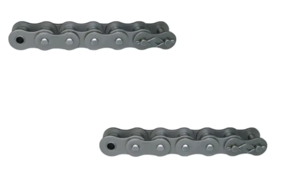
Begin with the physical requirement: use enough teeth for acceptable engagement while balancing the very large sprocket diameter that can result from large-pitch heavy chain. It is connected to low speed reduces dynamic impact but heavy chain pull still concentrates load where rollers contact teeth. At site level, very small sprockets increase articulation and tooth loading even at modest RPM. The avoidable outcome is saving space with too few teeth can shorten joint and sprocket life.
Inspect as follows: compare pitch, tooth count, wrap, sprocket material, and shaft envelope for several candidate chains. Release the step after you can choose geometry that spreads load over adequate teeth without exceeding package limits. Repeat the check after adjustment whenever the adjustment itself can change the measured condition.
Check shafts, bearings, and structural reaction
Translate chain pull into sprocket torque and bearing reaction and review hub, key, shaft, and frame stiffness. Why it matters: high chain force passes directly into the supporting structure and can exceed components that were acceptable in a faster lower-force drive. Field nuance: large overhung sprockets can also create bending load at the shaft. Failure mode: upgrading chain alone can move failure into bearings, keys, or supports.
Inspection: prepare a free-body diagram with chain force direction and bearing locations and calculate or verify supporting-component loads. Release condition: confirm the whole load path is rated for the corrected design force. Record the operating state and the reference points used for this check.
Make lubricant reach slowly moving loaded joints
Start by use a lubricant and application method that penetrates pin-bushing contacts even when there is little centrifugal distribution or frequent idle time. The mechanism is slow chains may not circulate oil quickly and heavily loaded joints can squeeze out lubricant during long dwell periods. In practice, static corrosion can develop when contaminated or wet chains sit unused. If the assumption is wrong, assuming low speed means little lubrication is needed can produce fretting and start-up wear.
Field check: inspect internal film after operating and after long shutdowns and check for dry or rusty pins. Accept the step when you can set lubrication and preservation practices based on load, environment, and idle periods rather than speed alone. Save the measured or observed condition so the result can be repeated later.
Inspect after jams and overload starts
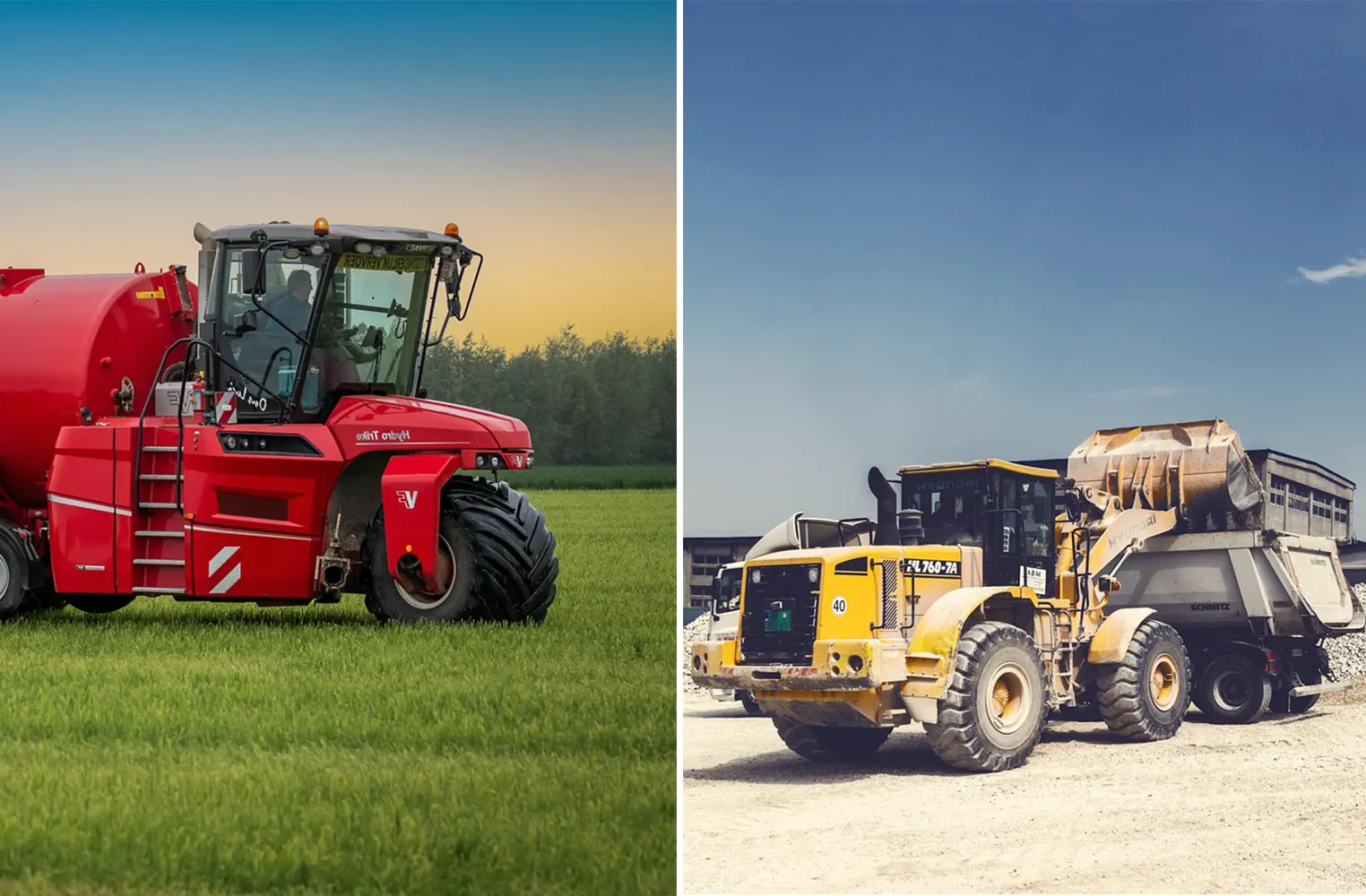
Use check plates, pins, rollers, sprockets, shaft alignment, and take-up after a severe stall or restart under load. This controls the decision because high-force slow systems often contain large stored torque and process resistance. On the machine, a clutch or motor may recover from a jam while the chain, key, or tooth has already been damaged. The practical risk is returning directly to service can turn hidden overload damage into fatigue failure.
Confirm it by doing this: inspect visible deformation, cracks, pin movement, tooth damage, and alignment after abnormal events. The evidence is sufficient when you can repair the full drive and revisit overload protection if the event is repeatable. Note the tool, location, and operating condition with the result.
Application verification table
| Decision point | Inspection or calculation | Acceptance evidence |
|---|---|---|
| Calculate chain pull explicitly | calculate speed from pitch, teeth, and RPM and then nominal chain pull from power and speed | use the resulting force as a cross-check against chain, sprocket, shaft, and bearing ratings |
| Use allowable-load and fatigue criteria | compare design load with the exact chain series allowable or rating data and review transient events separately | select a chain with documented operating capacity for the duty cycle |
| Review sprocket teeth and chain articulation | compare pitch, tooth count, wrap, sprocket material, and shaft envelope for several candidate chains | choose geometry that spreads load over adequate teeth without exceeding package limits |
| Check shafts, bearings, and structural reaction | prepare a free-body diagram with chain force direction and bearing locations and calculate or verify supporting-component loads | confirm the whole load path is rated for the corrected design force |
| Make lubricant reach slowly moving loaded joints | inspect internal film after operating and after long shutdowns and check for dry or rusty pins | set lubrication and preservation practices based on load, environment, and idle periods rather than speed alone |
| Inspect after jams and overload starts | inspect visible deformation, cracks, pin movement, tooth damage, and alignment after abnormal events | repair the full drive and revisit overload protection if the event is repeatable |
| For this article, do not close the job until the low-speed chain drive evidence and every critical mating interface are recorded together. | ||
For a wider view of the hardware around this problem, see review sprocket components for high-load drives. Use that page only as context for low-speed high-load chain drives; approve the real drive from measured interfaces, current ratings, and the machine duty described in this article.
Application risks that deserve design attention
Release check: use the resulting force as a cross-check against chain, sprocket, shaft, and bearing ratings.
Release check: select a chain with documented operating capacity for the duty cycle.
Release check: choose geometry that spreads load over adequate teeth without exceeding package limits.
Release check: confirm the whole load path is rated for the corrected design force.
Application FAQs
Release the application specification with operating limits
A finished application decision should let another engineer reproduce it without relying on memory. Keep low-speed chain drive, high chain pull, the final check for “Inspect after jams and overload starts,” and the governing catalog or drawing revision together. If another chain architecture becomes relevant, the chain drive engineering solutions is a starting point, not a replacement for those recorded inputs.
For an application-specific review, send the application data to the chain engineering team and identify what is known versus what remains uncertain. Include the values for low-speed chain drive and high chain pull, plus the current condition of allowable load. A supplier can then evaluate a bounded engineering question instead of trying to infer the machine from a chain designation alone.
Send the operating condition, low-speed chain drive, high chain pull, layout evidence, and the unresolved interface so the next decision is based on machine data rather than assumption.