Translate process duty into chain requirements
A chain-drive decision becomes much easier when the machine is reduced to measurable inputs instead of being described only as light, medium, or heavy duty. Conveyor chain selection starts with what the conveyor carries and how the chain supports or pulls it. The chain may transmit power at a drive station, carry attachments, roll on tracks, or perform several functions simultaneously.
Start at the machine, then use the industrial transmission chain options to identify candidates consistent with conveyor chain and chain pull. Before a candidate is accepted, calculate the maximum chain pull at the most highly loaded point using a documented conveyor method. This is deliberately different from choosing a familiar chain number first and trying to make the surrounding drive fit it later.
- Förderkette
- Treat this as a controlled variable; note its value, unit, operating state, and source in the job record.
- Chain Pull
- Verify this item against the physical drive and the current supplier data instead of estimating it from appearance.
- Attachments
- Use this parameter to reject unsuitable options early, then retain the verified value for the final specification.
- Take-Up
- Check this point at the machine and document any uncertainty that still requires a supplier drawing or manual.
- Roller Support
- Record this requirement with enough context that a second engineer can reproduce the same selection or diagnosis.
Standard roller, oversize roller, double-pitch, attachment, and engineering chains are optimized for different contact modes. Therefore, select a chain family whose rollers, bushings, and attachments match that motion.
Poor support increases friction, wear, and power demand.
Define the conveyed load and resistance
A reliable result starts when you calculate or estimate product weight, chain weight, friction, incline, acceleration, accumulation, and process resistance along the conveyor. The underlying reason is conveyor chain tension comes from more than motor power because the chain also moves its own mass and overcomes track friction. In service, start-up or product accumulation can raise tension above steady running values. An incorrect input may create sizing from motor kW alone can hide a high mechanical resistance or overloaded section.
Use the following field evidence: break the conveyor into loaded and return spans and record weights, coefficients, incline, and acceleration assumptions. Accept the result only if you can calculate the maximum chain pull at the most highly loaded point using a documented conveyor method. If the check is visual, add a dimension or operating observation whenever practical.
Choose the chain function and roller type
Establish the condition by choosing to decide whether the chain primarily transmits torque, carries product through attachments, rolls on rails, or slides on guides. It affects the drive because standard roller, oversize roller, double-pitch, attachment, and engineering chains are optimized for different contact modes. A useful constraint is that a chain chosen only from tensile capacity may have the wrong roller diameter or attachment geometry for the track. Getting it wrong can produce poor support increases friction, wear, and power demand.
Confirm the condition this way: inspect track width, rail material, product support, and return-path geometry and define how each chain component contacts the conveyor. The step passes when you can select a chain family whose rollers, bushings, and attachments match that motion. Keep the evidence beside the chain designation and machine location in the maintenance record.
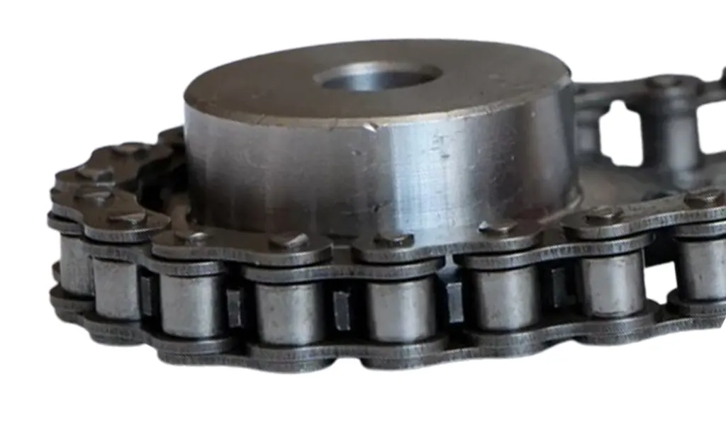
Specify attachments as a controlled pattern
Begin with the physical requirement: define attachment type, hole size, orientation, side, pitch spacing, fixture load, and tolerances. It is connected to attachments transfer product or fixture loads into the chain and influence load distribution and indexing. At site level, uneven attachment spacing or stiff fixtures can twist the chain and prevent smooth articulation. The avoidable outcome is ordering a correct base chain with the wrong attachment schedule makes the conveyor unusable.
Inspect as follows: create a pitch-by-pitch attachment drawing and verify fixture centers against the process layout. Release the step after you can approve supplier drawings before production and record attachment orientation in spare specifications. Repeat the check after adjustment whenever the adjustment itself can change the measured condition.
Select sprockets for stable engagement
Verify tooth count, roller diameter, effective teeth, material, hardening if needed, shaft mounting, and wrap. Why it matters: conveyor sprockets may see fewer working teeth, high accumulated tension, and abrasive material around the pockets. Field nuance: small tooth counts increase polygonal motion and can disturb indexing or product transfer. Failure mode: poor tooth design or material buildup creates chain climb and shock.
Inspection: inspect available sprocket diameter, shaft size, tooth-pocket cleaning, and required indexing. Release condition: choose matched sprockets and provide access to inspect or replace wear components. Record the operating state and the reference points used for this check.
Design take-up for long centers and parallel chains
Start by provide enough adjustment for installation, seating, wear, thermal movement, and equal left-right tension where two chains run in parallel. The mechanism is conveyors often have longer centers than compact transmission drives and uneven take-up can skew crossbars or fixtures. In practice, independent screw adjustments can put one chain ahead of the other and overload attachments. If the assumption is wrong, take-up that only tightens slack can create misalignment and uneven load sharing.
Field check: measure or design synchronized take-up travel and reference marks on both sides. Accept the step when you can confirm both chains remain timed and shafts parallel throughout the adjustment range. Save the measured or observed condition so the result can be repeated later.
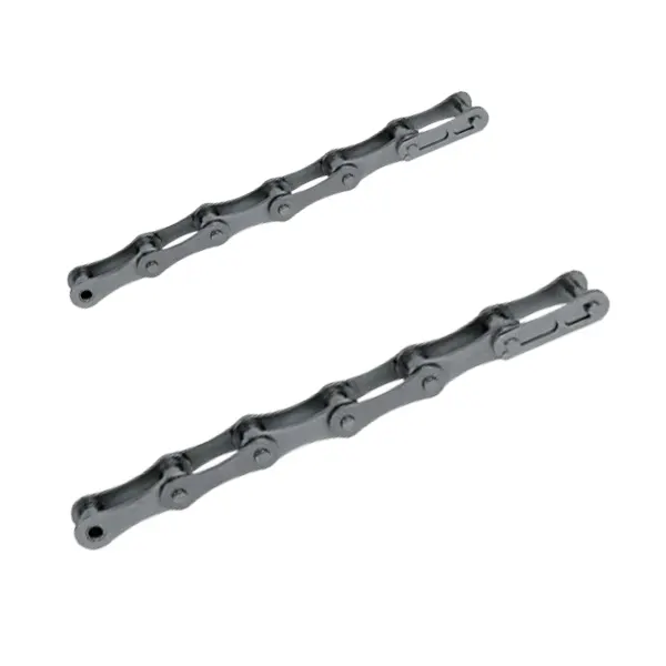
Make maintenance access part of selection
Use allow inspection of wear elongation, rollers, attachment fasteners, sprocket teeth, lubrication points, and take-up without major disassembly. This controls the decision because conveyors fail when components that need routine attention are hidden behind process equipment or guarding. On the machine, dirty or food-process conveyors may need frequent cleaning that conflicts with conventional lubrication. The practical risk is a high-capacity chain is a poor choice if technicians cannot maintain its joints safely.
Confirm it by doing this: walk the conveyor route and mark every inspection and lubrication point plus safe access method. The evidence is sufficient when you can select chain, guards, and lubrication so condition checks can be performed consistently. Note the tool, location, and operating condition with the result.
Application verification table
| Decision point | Inspection or calculation | Acceptance evidence |
|---|---|---|
| Define the conveyed load and resistance | break the conveyor into loaded and return spans and record weights, coefficients, incline, and acceleration assumptions | calculate the maximum chain pull at the most highly loaded point using a documented conveyor method |
| Choose the chain function and roller type | inspect track width, rail material, product support, and return-path geometry and define how each chain component contacts the conveyor | select a chain family whose rollers, bushings, and attachments match that motion |
| Specify attachments as a controlled pattern | create a pitch-by-pitch attachment drawing and verify fixture centers against the process layout | approve supplier drawings before production and record attachment orientation in spare specifications |
| Select sprockets for stable engagement | inspect available sprocket diameter, shaft size, tooth-pocket cleaning, and required indexing | choose matched sprockets and provide access to inspect or replace wear components |
| Design take-up for long centers and parallel chains | measure or design synchronized take-up travel and reference marks on both sides | confirm both chains remain timed and shafts parallel throughout the adjustment range |
| Make maintenance access part of selection | walk the conveyor route and mark every inspection and lubrication point plus safe access method | select chain, guards, and lubrication so condition checks can be performed consistently |
| For this article, do not close the job until the conveyor chain evidence and every critical mating interface are recorded together. | ||
Some failures that look like chain problems are controlled by neighboring hardware. review chain-driven conveyor application context helps illustrate that broader transmission chain for conveyors context, while the acceptance criteria still come from the actual chain, sprocket, tensioning arrangement, and OEM documentation.
Application risks that deserve design attention
Release check: calculate the maximum chain pull at the most highly loaded point using a documented conveyor method.
Release check: select a chain family whose rollers, bushings, and attachments match that motion.
Release check: approve supplier drawings before production and record attachment orientation in spare specifications.
Release check: choose matched sprockets and provide access to inspect or replace wear components.
Application FAQs
Release the application specification with operating limits
Release the work only when the record connects conveyor chain and chain pull to the physical condition verified in “Make maintenance access part of selection.” Include photos or measurements where they clarify the interface, and reference the document that owns any exact limit. The industrial chain drive solutions can then be used to explore alternatives without losing the original engineering basis.
Do not hide a remaining assumption inside the purchase description. send the application data to the chain engineering team with the machine duty, measured interfaces, photographs, and the unresolved question around attachments. A clear uncertainty is actionable; an undocumented guess becomes a future troubleshooting problem.
Send the operating condition, conveyor chain, chain pull, layout evidence, and the unresolved interface so the next decision is based on machine data rather than assumption.