Prepare for a controlled installation
The quickest way to make this decision reliable is to define the operating condition first and postpone the chain number until the interfaces are known. Gravity changes a vertical chain drive. Slack does not settle harmlessly on a lower horizontal span, and wear can allow the chain to lose stable sprocket engagement unless take-up and guidance are designed deliberately.
مراجعة مجموعة منتجات السلاسل المختارة can save time, but only when the search is constrained by verified vertical chain drive and automatic tensioner. The engineering gate for this topic is to choose the layout and tensioner strategy for every permitted operating condition; anything that fails that gate remains a hypothesis, not a released specification.
Confirm which shaft is driving and the torque direction: vertical drives can respond differently when the lower shaft drives because gravity and chain tension act along the same path.
Maintain adequate sprocket wrap: vertical tensioners can easily change tangency and reduce engagement if placed only for packaging convenience.
- Vertical Chain Drive
- قم بتسجيل هذه البيانات من رسم أو قياس أو حساب أو سجل تشغيل قبل اتخاذ القرار.
- Automatic Tensioner
- تعامل مع هذا كمتغير خاضع للتحكم؛ دوّن قيمته ووحدته وحالة تشغيله ومصدره في سجل المهمة.
- ارفع
- تحقق من هذا العنصر مقابل محرك الأقراص الفعلي وبيانات المورد الحالية بدلاً من تقديره من المظهر.
- Chain Wrap
- استخدم هذه المعلمة لرفض الخيارات غير المناسبة مبكراً، ثم احتفظ بالقيمة التي تم التحقق منها للمواصفات النهائية.
- Lubrication
- تحقق من هذه النقطة في الآلة وقم بتوثيق أي غموض لا يزال يتطلب رسمًا أو دليلًا من المورد.
Confirm which shaft is driving and the torque direction
Identify driver location, rotation, start-stop behavior, and whether the drive can reverse. Why it matters: vertical drives can respond differently when the lower shaft drives because gravity and chain tension act along the same path. Field nuance: reversing duty may swap the effective tight and slack conditions and can complicate fixed idler placement. Failure mode: assuming a single direction can leave the chain uncontrolled during coast or reverse.
Inspection: draw the chain path with arrows for gravity and both torque directions and mark the expected tension state of each span. Release condition: choose the layout and tensioner strategy for every permitted operating condition. Record the operating state and the reference points used for this check.
Provide positive slack control
Start by use an automatic tensioner, idler, or adjustable shaft arrangement recommended for vertical service. The mechanism is gravity does not create the same stable lower slack loop as a horizontal drive and wear elongation can accumulate where it threatens engagement. In practice, a fixed initial setting may become ineffective as the chain seats and wears. If the assumption is wrong, excess free chain can climb teeth, whip, or fall away from the sprocket during stopping.
Field check: measure available take-up travel and select a device whose working range covers installation and wear adjustment. Accept the step when you can verify controlled engagement at new-chain and maximum permitted wear positions. Save the measured or observed condition so the result can be repeated later.
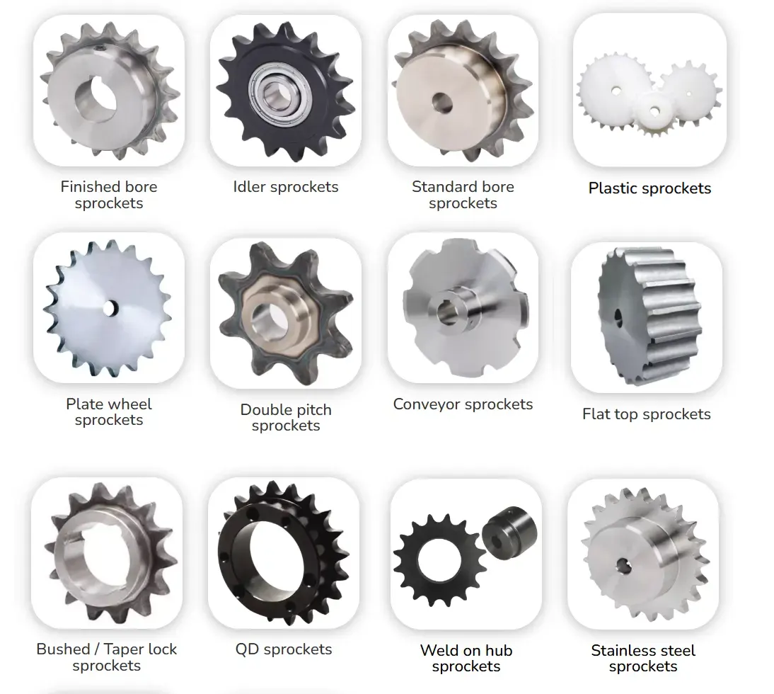
Maintain adequate sprocket wrap
Use position take-up and guides so both sprockets retain the wrap required for stable load transfer. This controls the decision because vertical tensioners can easily change tangency and reduce engagement if placed only for packaging convenience. On the machine, large ratio differences can further reduce wrap on the small sprocket. The practical risk is poor wrap increases tooth load and can allow jumping during transient slack.
Confirm it by doing this: model the chain path at both ends of tensioner travel and measure wrap on the smaller sprocket. The evidence is sufficient when you can set geometry so minimum wrap remains acceptable throughout service. Note the tool, location, and operating condition with the result.
Avoid excessive continuous preload
Work from use only enough tensioner force to prevent loss of engagement and control span motion. The engineering link is high preload adds to chain, bearing, and shaft forces continuously and can accelerate pin-bushing wear. One useful detail is that a strong spring can make the drive look stable while hiding an unnecessarily high load. Otherwise, over-tensioning reduces life and may increase heat or noise.
Verify at the drive: check tensioner force, bearing reaction, and chain freedom at several positions through its stroke. Close this check only after you can follow the selected component guidance and preserve detectable chain articulation without a taut span. Keep photographs or dimensions when they help preserve the interface condition.
Design lubrication for gravity effects
Base the decision on apply lubricant where it can enter pin-bushing joints and ensure gravity does not simply drain it away before penetration. It matters because vertical orientation changes oil flow and can leave upper joints dry or lower areas over-oiled. During service, manual application at one convenient point may not distribute uniformly around the loop. A poor assumption can cause uneven lubrication can create localized wear and different elongation rates.
Use this confirmation: inspect joint film at upper and lower portions after operation and look for dry pins, runoff, or contamination. Proceed when you can adjust application location, viscosity, or delivery system until joint lubrication is consistent around the loop. If readings vary around the chain or sprocket, retain the spread instead of hiding it in one average.
Add retention and inspection features
The controlling action is to provide guards, guide stops, or containment where a loose or broken chain could fall or disengage dangerously. Its significance comes from vertical chain failure can allow components to move under gravity and can release chain from the sprocket path. In the field, maintenance access also needs a safe way to support the chain during service. The failure consequence is treating the guard only as a pinch-point cover can miss chain-drop and stored-energy hazards.
Check the hardware directly: review failure paths, chain-removal procedure, support points, and inspection visibility during design. Approval requires that you can confirm the guard and maintenance method contain the chain and control gravitational loads during service. Write down any uncertainty that still needs a drawing, manual, or supplier response.
Installation acceptance table
| نقطة القرار | الفحص أو الحساب | أدلة القبول |
|---|---|---|
| Confirm which shaft is driving and the torque direction | draw the chain path with arrows for gravity and both torque directions and mark the expected tension state of each span | choose the layout and tensioner strategy for every permitted operating condition |
| Provide positive slack control | measure available take-up travel and select a device whose working range covers installation and wear adjustment | verify controlled engagement at new-chain and maximum permitted wear positions |
| Maintain adequate sprocket wrap | model the chain path at both ends of tensioner travel and measure wrap on the smaller sprocket | set geometry so minimum wrap remains acceptable throughout service |
| Avoid excessive continuous preload | check tensioner force, bearing reaction, and chain freedom at several positions through its stroke | follow the selected component guidance and preserve detectable chain articulation without a taut span |
| Design lubrication for gravity effects | inspect joint film at upper and lower portions after operation and look for dry pins, runoff, or contamination | adjust application location, viscosity, or delivery system until joint lubrication is consistent around the loop |
| Add retention and inspection features | review failure paths, chain-removal procedure, support points, and inspection visibility during design | confirm the guard and maintenance method contain the chain and control gravitational loads during service |
| For this article, do not close the job until the vertical chain drive evidence and every critical mating interface are recorded together. | ||
يكون اختيار المكونات في أقوى حالاته عندما لا تتم مراجعة السلسلة بمعزل عن غيرها. review tensioner options for vertical chain layouts offers related vertical roller-chain drive setup context; keep the final engineering check tied to the exact standard family, manufacturer table, and measured installation.
Installation faults to eliminate
Release check: choose the layout and tensioner strategy for every permitted operating condition.
Release check: verify controlled engagement at new-chain and maximum permitted wear positions.
Release check: set geometry so minimum wrap remains acceptable throughout service.
Release check: follow the selected component guidance and preserve detectable chain articulation without a taut span.
Installation FAQs
Commission the drive from a known baseline
The strongest handoff for this installation topic is a short evidence package: verified vertical chain drive, verified automatic tensioner, the result of “Add retention and inspection features,” and the exact source of any chain-series-specific limit. Broader alternatives on the حلول سلسلة نقل الطاقة ينبغي مقارنتها بنفس الحزمة بدلاً من مقارنتها بأوصاف الكتالوج العامة.
For vertical roller-chain drive setup, if take-up has not been verified, send the application data to the chain engineering team with the evidence collected in the preceding checks. State the operating condition, measured dimensions, current sprocket condition, and intended maintenance or design action so the remaining check can be closed before the machine returns to service.
Send the operating condition, vertical chain drive, automatic tensioner, layout evidence, and the unresolved interface so the next decision is based on machine data rather than assumption.