Define inputs before using the equation
For an industrial drive, the useful question is not whether a chain looks strong enough; it is whether the selected chain, sprockets, lubrication, and layout work together under the real duty. A service factor is a structured correction for duty severity, not a universal safety factor. It connects the type of prime mover and driven machine to the rating-table input used for chain selection.
Use the transmission chain product range as a map of available chain families only after you have captured service factor and design power. For this topic, the first release condition is specific: select the driver category that matches the manufacturer definitions rather than inventing a new factor. That sequence keeps catalog browsing from turning into a pitch-only or appearance-only substitution.
- Service Factor
- Use this parameter to reject unsuitable options early, then retain the verified value for the final specification.
- Design Power
- Check this point at the machine and document any uncertainty that still requires a supplier drawing or manual.
- Shock Load
- Record this requirement with enough context that a second engineer can reproduce the same selection or diagnosis.
- Driver Type
- Capture this input from a drawing, measurement, calculation, or operating record before the decision advances.
- Driven Machine
- Treat this as a controlled variable; note its value, unit, operating state, and source in the job record.
Identify the prime mover correctly
A reliable result starts when you classify the actual driver such as electric motor, engine, or other source using the categories in the selected chain manufacturer table. The underlying reason is different drivers can impose different torque variation and starting characteristics. In service, a VFD-controlled motor may operate very differently from a direct-on-line start even though both are electric. An incorrect input may create placing the driver in the wrong category can understate or overstate design power.
Use the following field evidence: review the motor, clutch, coupling, and control method and note how torque is applied during start and running. Accept the result only if you can select the driver category that matches the manufacturer definitions rather than inventing a new factor. If the check is visual, add a dimension or operating observation whenever practical.
Classify the driven machine by load character
Establish the condition by choosing to identify whether the load is uniform, moderate shock, heavy shock, reciprocating, reversing, or otherwise defined by the supplier table. It affects the drive because the driven process often determines the amplitude and frequency of chain tension changes. A useful constraint is that a conveyor with steady product flow and a crusher with impact loading should not use the same correction just because motor power is equal. Getting it wrong can produce misclassifying the machine can place the chain below the fatigue demand of the duty.
Confirm the condition this way: observe starts, jams, product impacts, reciprocation, and torque fluctuations and compare them with the table examples. The step passes when you can document the chosen driven-machine category and the evidence supporting it. Keep the evidence beside the chain designation and machine location in the maintenance record.
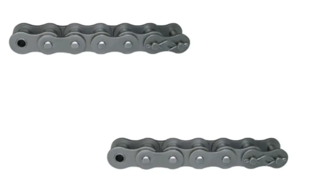
Multiply base power only after the duty is classified
Begin with the physical requirement: apply the published service factor to transmitted horsepower or kilowatts to obtain design power when that is the manufacturer method. It is connected to keeping base power and correction separate makes the selection auditable. At site level, adding several arbitrary margins can double-count conservatism while omitting the actual duty factor can under-size the drive. The avoidable outcome is a hidden margin makes later troubleshooting difficult because no one knows the design basis.
Inspect as follows: show base power, service factor, and design power as separate lines in the calculation. Release the step after you can use design power as the input to the corresponding chain rating table. Repeat the check after adjustment whenever the adjustment itself can change the measured condition.
Do not use one factor across unrelated manufacturers
Follow the service-factor definitions and rating method belonging to the chain series being selected. Why it matters: rating tables and correction factors are developed as a system and may use different assumptions. Field nuance: copying a factor from one catalog into another rating table can mix incompatible methods. Failure mode: a numerically familiar factor can create a false sense of precision.
Inspection: keep the catalog revision and factor table with the selection record. Release condition: verify the factor and rating table come from the same supplier method or a documented equivalent engineering basis. Record the operating state and the reference points used for this check.
Check transient events the table may not fully capture
Start by separately review emergency stops, jams, clutch engagement, back-driving, and unusual start frequency when they are outside normal table assumptions. The mechanism is a generic service category cannot describe every severe or infrequent event. In practice, high-inertia systems can produce short torque peaks much higher than steady running load. If the assumption is wrong, a chain can pass design-power selection yet still be vulnerable to a rare mechanical shock.
Field check: estimate or measure transient torque where failure consequence is high and review it with the chain and machine supplier. Accept the step when you can confirm the selected chain and sprocket system can tolerate both normal fatigue duty and credible transients. Save the measured or observed condition so the result can be repeated later.
Use failure evidence to validate the service classification
Use compare the calculated design duty with plate fractures, pin damage, roller cracking, or repeated overload history. This controls the decision because field failures can reveal that the original duty classification was incomplete. On the machine, a process throughput increase or control change may have altered shock severity since commissioning. The practical risk is reusing the old service factor after a process change can repeat the failure.
Confirm it by doing this: review production history, motor current or torque trends, and damaged components before re-rating. The evidence is sufficient when you can update the service classification whenever the machine duty materially changes. Note the tool, location, and operating condition with the result.

Calculation and validation table
| Decision point | Inspection or calculation | Acceptance evidence |
|---|---|---|
| Identify the prime mover correctly | review the motor, clutch, coupling, and control method and note how torque is applied during start and running | select the driver category that matches the manufacturer definitions rather than inventing a new factor |
| Classify the driven machine by load character | observe starts, jams, product impacts, reciprocation, and torque fluctuations and compare them with the table examples | document the chosen driven-machine category and the evidence supporting it |
| Multiply base power only after the duty is classified | show base power, service factor, and design power as separate lines in the calculation | use design power as the input to the corresponding chain rating table |
| Do not use one factor across unrelated manufacturers | keep the catalog revision and factor table with the selection record | verify the factor and rating table come from the same supplier method or a documented equivalent engineering basis |
| Check transient events the table may not fully capture | estimate or measure transient torque where failure consequence is high and review it with the chain and machine supplier | confirm the selected chain and sprocket system can tolerate both normal fatigue duty and credible transients |
| Use failure evidence to validate the service classification | review production history, motor current or torque trends, and damaged components before re-rating | update the service classification whenever the machine duty materially changes |
| For this article, do not close the job until the service factor evidence and every critical mating interface are recorded together. | ||
The neighboring component matters because chain behavior depends on the complete drive. review sprocket options after the duty factor is established provides additional product context for roller-chain service factor; use it to frame questions, then confirm dimensions and ratings from the exact component drawing used on the machine.
Calculation mistakes that distort selection
Release check: select the driver category that matches the manufacturer definitions rather than inventing a new factor.
Release check: document the chosen driven-machine category and the evidence supporting it.
Release check: use design power as the input to the corresponding chain rating table.
Release check: verify the factor and rating table come from the same supplier method or a documented equivalent engineering basis.
Calculation FAQs
Release the result only after a physical cross-check
Close this calculation task with a traceable record of service factor, design power, and the inspection result for “Use failure evidence to validate the service classification.” The release note should state the operating condition used for the check and identify the drawing, rating table, or machine document that set any model-specific limit. The chain-and-sprocket drive options can provide broader chain-drive context when a neighboring component also needs review.
If roller-chain service factor still contains an unresolved variable, send the application data to the chain engineering team with the operating state, the relevant measurements, photographs of the chain and sprockets, and the unknown item clearly marked. For this topic, pay particular attention to shock load. Resolving that gap before purchase or restart is usually cheaper than diagnosing a second problem created by an assumed value.
Send the operating condition, service factor, design power, layout evidence, and the unresolved interface so the next decision is based on machine data rather than assumption.