Set up a defensible measurement
A chain-drive decision becomes much easier when the machine is reduced to measurable inputs instead of being described only as light, medium, or heavy duty. A replacement chain is only interchangeable when the critical geometry matches. Measuring several pitches and the mating sprocket is more reliable than identifying a chain from one dimension or a faded number.
A practical way to use the roller and transmission chain range is to narrow the product family after the machine has supplied evidence for chain pitch and roller diameter. The selected option should then survive this check: match the calculated pitch to the dimensional table for the intended ANSI or ISO family. If it does not, return to the duty or geometry rather than adding an arbitrary safety margin.
- Chain Pitch
- 이를 제어 변수로 취급하고, 작업 기록에 해당 값, 단위, 작동 상태 및 출처를 기록하십시오.
- Roller Diameter
- 외관만 보고 판단하지 말고, 해당 제품의 실제 드라이브와 현재 공급업체 데이터를 대조하여 확인하십시오.
- Inner Width
- 이 매개변수를 사용하여 부적합한 옵션을 조기에 제외하고, 검증된 값을 최종 사양에 사용할 수 있습니다.
- Strand Count
- 기계에서 해당 부분을 점검하고, 공급업체 도면이나 설명서가 필요한 불확실한 사항은 모두 기록해 두십시오.
- Measurement Span
- 두 번째 엔지니어가 동일한 선택 또는 진단을 재현할 수 있도록 이 요구 사항을 충분한 맥락과 함께 기록하십시오.
One-pitch caliper readings magnify placement error and worn joints can vary locally. The practical release check is to match the calculated pitch to the dimensional table for the intended ANSI or ISO family.
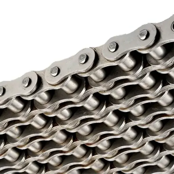
Establish pitch from a multi-link measurement
Work from lightly tension a straight clean chain span and measure pin-center distance across several pitches. The engineering link is one-pitch caliper readings magnify placement error and worn joints can vary locally. One useful detail is that ten or more pitches give a more stable average when space allows. Otherwise, an incorrect pitch will prevent proper seating and create impact at the sprocket.
Verify at the drive: measure between repeatable pin centers or equivalent roller references on a straight span and divide by the number of pitches. Close this check only after you can match the calculated pitch to the dimensional table for the intended ANSI or ISO family. Keep photographs or dimensions when they help preserve the interface condition.
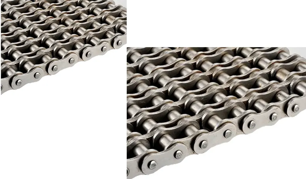
Measure roller diameter at more than one location
Base the decision on use a clean caliper or micrometer across the roller outside diameter without clamping hard enough to distort the reading. It matters because roller diameter controls how the chain enters the sprocket tooth space and separates families that can share nominal pitch. During service, a worn roller may be smaller than new nominal size, so record the largest intact roller and compare several links. A poor assumption can cause a chain can appear to share pitch yet sit too deep or contact the wrong tooth surface.
Use this confirmation: measure several rollers away from visibly damaged areas and compare for flat spots or taper. Proceed when you can confirm the roller diameter agrees with the same standard series as the measured pitch. If readings vary around the chain or sprocket, retain the spread instead of hiding it in one average.
Measure inner width between the inner link plates
The controlling action is to place the caliper tips on the flat inside faces of the inner plates and keep the jaws square to the chain centerline. Its significance comes from inner width must clear sprocket tooth thickness while controlling excessive lateral movement. In the field, burrs, plate deformation, and corrosion scale can bias a narrow reading. The failure consequence is a too-narrow replacement can bind on the sprocket while an unrelated wider series may have poor guidance.
Check the hardware directly: repeat the measurement at multiple links and note whether the plates are parallel. Approval requires that you can match inner width and roller diameter together rather than treating either as optional. Write down any uncertainty that still needs a drawing, manual, or supplier response.
Confirm strand count and transverse geometry
First, count the roller rows and measure the transverse pitch between strands when the chain is duplex, triplex, or wider. That step is tied to multiple-strand chains require matching sprockets and side clearances across the whole width. A practical observation is that a duplex chain is not simply two independent simplex chains mounted side by side. Missing it can lead to ordering the wrong strand arrangement can make the chain impossible to install even when pitch is correct.
For evidence, inspect the chain end-on and measure overall pin width plus center spacing between roller rows. Finish when you can confirm the sprocket has the same number of tooth rows and compatible transverse spacing. Retain enough context to distinguish a new-chain dimension from a wear-affected measurement.
Use the sprocket as a second identification source
Treat inspect tooth count, tooth form, sprocket thickness, bore arrangement, and any readable markings as the control point. The reason is the mating sprocket often reveals which chain geometry the machine was designed around. Real installations also show that hooked teeth can distort visual judgment, so use unworn areas and drawings where possible. The likely consequence of error is using a new chain on the wrong or severely worn sprocket can accelerate wear immediately.
Make the check at the machine: measure tooth count and accessible sprocket dimensions, then photograph the tooth profile and hub. The release criterion is to verify both chain dimensions and sprocket geometry against one standard family. Record whether the drive was stopped, loaded, warm, cold, clean, or contaminated as relevant.
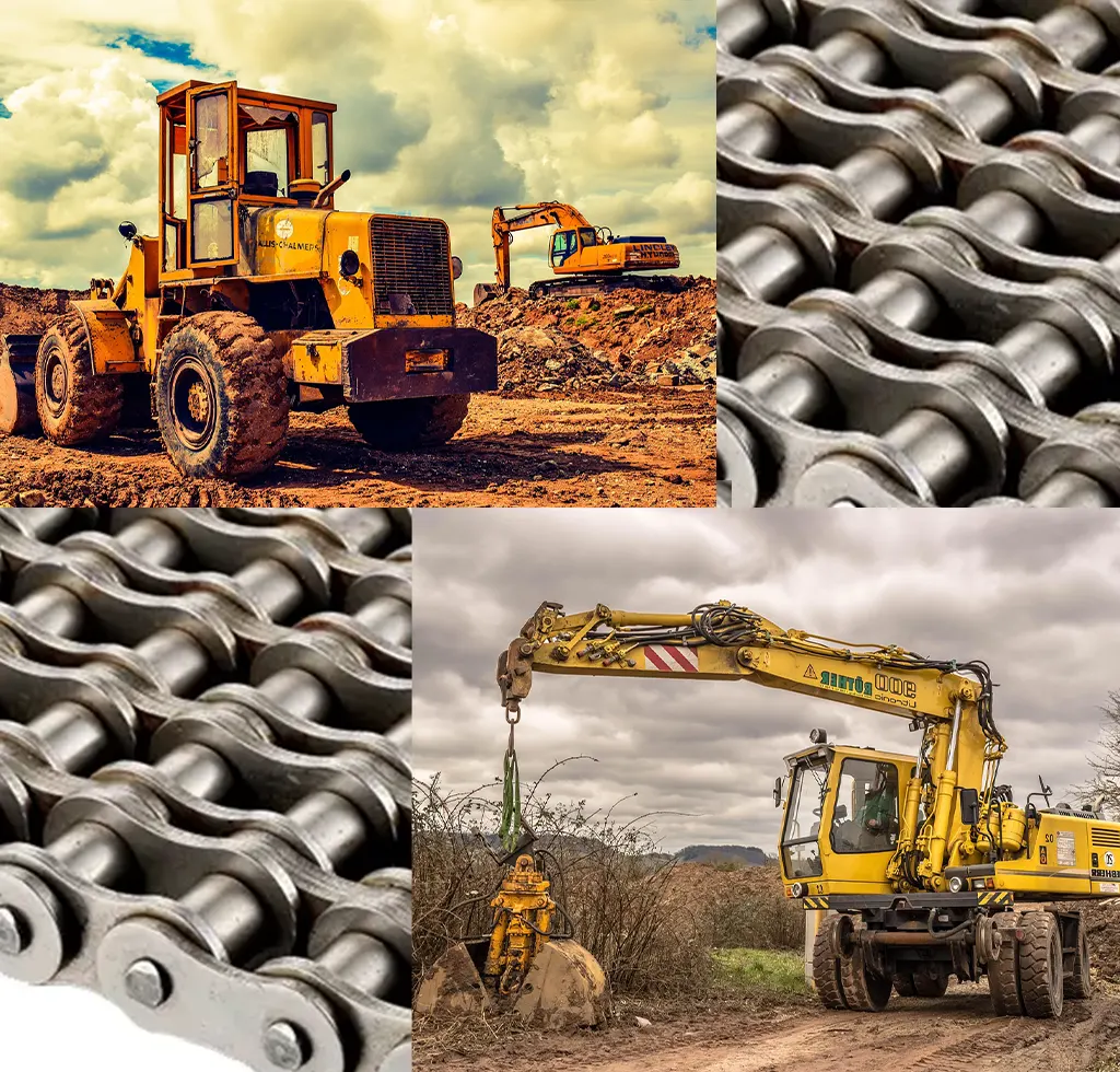
Create a replacement-ready measurement record
Do not choose the hardware until you record units, tools, number of pitches measured, chain condition, strand count, and all measured dimensions with photos. This matters because a supplier cannot resolve an ambiguous chain from a single pitch number. Remember that noting whether values came from a worn chain or a new spare prevents false precision. If ignored, missing context can lead to a technically plausible but incompatible substitute.
Validate with a repeatable observation: put the measurements in a simple table and include the machine duty and any stamped chain code. Move on after you can obtain a supplier drawing and check every controlling dimension before ordering. Preserve the source of any numerical limit that belongs to a specific chain series.
Measurement record and cross-checks
| 결정의 순간 | 검사 또는 계산 | 수용 증거 |
|---|---|---|
| Establish pitch from a multi-link measurement | measure between repeatable pin centers or equivalent roller references on a straight span and divide by the number of pitches | match the calculated pitch to the dimensional table for the intended ANSI or ISO family |
| Measure roller diameter at more than one location | measure several rollers away from visibly damaged areas and compare for flat spots or taper | confirm the roller diameter agrees with the same standard series as the measured pitch |
| Measure inner width between the inner link plates | repeat the measurement at multiple links and note whether the plates are parallel | match inner width and roller diameter together rather than treating either as optional |
| Confirm strand count and transverse geometry | inspect the chain end-on and measure overall pin width plus center spacing between roller rows | confirm the sprocket has the same number of tooth rows and compatible transverse spacing |
| Use the sprocket as a second identification source | measure tooth count and accessible sprocket dimensions, then photograph the tooth profile and hub | verify both chain dimensions and sprocket geometry against one standard family |
| Create a replacement-ready measurement record | put the measurements in a simple table and include the machine duty and any stamped chain code | obtain a supplier drawing and check every controlling dimension before ordering |
| For this article, do not close the job until the chain pitch evidence and every critical mating interface are recorded together. | ||
When the decision extends beyond the chain itself, compare small-pitch roller-chain identification context is a useful adjacent-hardware reference for roller chain size identification. It is not a substitute for checking tooth geometry, mounting, capacity, and the selected chain standard on the final drawing.
Measurement errors that cause wrong replacements
Release check: match the calculated pitch to the dimensional table for the intended ANSI or ISO family.
Release check: confirm the roller diameter agrees with the same standard series as the measured pitch.
Release check: match inner width and roller diameter together rather than treating either as optional.
Release check: confirm the sprocket has the same number of tooth rows and compatible transverse spacing.
Measurement and replacement FAQs
Turn measurements into an orderable specification
The output should be more useful than a part number. Record chain pitch, roller diameter, the condition found during “Create a replacement-ready measurement record,” and the evidence used to accept or reject the change. That makes the decision auditable after the next shutdown. Use the industrial drive-chain capabilities to compare other transmission-chain families only when the same duty data is carried forward.
Where the final answer still depends on missing machine data, send the application data to the chain engineering team. Include the duty, speed, geometry and inspection evidence that led to the current conclusion, with inner width called out separately. The goal is to obtain a drawing-level answer before hardware is ordered or an adjustment becomes the new baseline.
Send the operating condition, chain pitch, roller diameter, layout evidence, and the unresolved interface so the next decision is based on machine data rather than assumption.