Build the selection envelope
A chain-drive decision becomes much easier when the machine is reduced to measurable inputs instead of being described only as light, medium, or heavy duty. Cranked-link transmission chains are used where robust joints and severe duty matter, but selection still requires a quantified load case and matched sprockets. A shock rating cannot be inferred from chain mass or plate thickness alone.
The available transmission chain families is most useful once the problem statement includes cranked-link chain and shock load. In this article the controlling verification is to define a design load case that includes the actual transient duty. Keeping those facts together gives purchasing and maintenance the same technical basis for the next action.
- Cranked-Link Chain
- Treat this as a controlled variable; note its value, unit, operating state, and source in the job record.
- Shock Load
- Verify this item against the physical drive and the current supplier data instead of estimating it from appearance.
- Chain Pull
- Use this parameter to reject unsuitable options early, then retain the verified value for the final specification.
- Fatigue Loading
- Check this point at the machine and document any uncertainty that still requires a supplier drawing or manual.
- Sprocket Engagement
- Record this requirement with enough context that a second engineer can reproduce the same selection or diagnosis.
Quantify normal and transient chain pull
A reliable result starts when you calculate steady chain pull from transmitted power and chain speed, then identify start-up, jam, reversing, or impact events that raise the load. The underlying reason is shock-loaded drives fail from repeated dynamic events as well as steady tension. In service, motor torque curves, clutch behavior, flywheel inertia, and process jams can dominate the peak condition. An incorrect input may create using only average production power can understate the load that damages pins or plates.
Use the following field evidence: review motor and reducer data, operating logs, and observed jam or start behavior and convert known torque to chain pull at the pitch radius. Accept the result only if you can define a design load case that includes the actual transient duty. If the check is visual, add a dimension or operating observation whenever practical.
Use allowable working data for the exact chain series
Establish the condition by choosing to select from manufacturer allowable-load or power data for the cranked-link design and operating speed. It affects the drive because ultimate tensile strength is not an operating rating and does not describe repeated fatigue loading. A useful constraint is that heavy-duty families can differ in heat treatment, pin construction, plate geometry, and allowable articulation. Getting it wrong can produce choosing by break load alone can create short fatigue life despite a high tensile number.
Confirm the condition this way: locate the operating point in the supplier selection method and note any service or shock factors. The step passes when you can confirm the chain is rated for repeated duty, not merely capable of surviving one pull test. Keep the evidence beside the chain designation and machine location in the maintenance record.
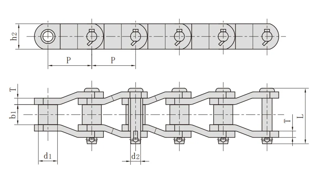
Match the mating sprocket and articulation geometry
Begin with the physical requirement: verify chain pitch, roller or bushing dimensions, sprocket tooth profile, tooth count, and wrap. It is connected to severe shock becomes more damaging when the chain articulates aggressively around a very small sprocket. At site level, worn tooth pockets or incorrect root geometry can concentrate impact on a few links. The avoidable outcome is a strong chain on poor sprockets can still suffer roller, bushing, or plate damage.
Inspect as follows: inspect tooth wear patterns and compare the sprocket drawing with the chosen chain series. Release the step after you can use sprockets specifically matched to the cranked-link chain and duty. Repeat the check after adjustment whenever the adjustment itself can change the measured condition.
Check lubrication under impact and contamination
Deliver lubricant into the pin-bushing joint while preventing abrasive debris from becoming grinding paste. Why it matters: shock raises contact stress while contamination and inadequate oil accelerate joint wear. Field nuance: heavy-duty applications such as aggregate or process equipment often combine shock with dust or grit. Failure mode: strength upgrades can be defeated by rapid wear elongation and stiff joints.
Inspection: inspect lubricant penetration, color, debris, and joint freedom at several locations around the chain. Release condition: design guarding and lubrication so the joints stay supplied without trapping abrasive contamination. Record the operating state and the reference points used for this check.
Inspect link articulation and assembly details
Start by verify every link pivots freely, connecting components are correctly installed, and no plates show peening or side contact. The mechanism is cranked-link chains depend on consistent articulation through the full strand. In practice, field assembly damage or a stiff joint can create a local load spike during sprocket entry. If the assumption is wrong, one binding link can become the origin of repeated impact and eventual fatigue failure.
Field check: rotate the unloaded drive by hand or inch it safely and watch each link enter and leave both sprockets. Accept the step when you can remove any source of binding and confirm connecting components match the exact series. Save the measured or observed condition so the result can be repeated later.

Plan replacement around system damage, not just chain breakage
Use inspect sprockets, shafts, bearings, guards, and take-up after any severe overload event. This controls the decision because a jam or impact large enough to damage chain may also bend a shaft, move a bearing, or deform teeth. On the machine, installing a new strand into an altered drive can reproduce the failure immediately. The practical risk is hidden alignment or tooth damage can shorten the life of expensive heavy-duty chain.
Confirm it by doing this: measure alignment and runout and inspect tooth profiles after overloads. The evidence is sufficient when you can release the drive only after the entire load path is restored to its intended geometry. Note the tool, location, and operating condition with the result.
Candidate verification table
| Decision point | Inspection or calculation | Acceptance evidence |
|---|---|---|
| Quantify normal and transient chain pull | review motor and reducer data, operating logs, and observed jam or start behavior and convert known torque to chain pull at the pitch radius | define a design load case that includes the actual transient duty |
| Use allowable working data for the exact chain series | locate the operating point in the supplier selection method and note any service or shock factors | confirm the chain is rated for repeated duty, not merely capable of surviving one pull test |
| Match the mating sprocket and articulation geometry | inspect tooth wear patterns and compare the sprocket drawing with the chosen chain series | use sprockets specifically matched to the cranked-link chain and duty |
| Check lubrication under impact and contamination | inspect lubricant penetration, color, debris, and joint freedom at several locations around the chain | design guarding and lubrication so the joints stay supplied without trapping abrasive contamination |
| Inspect link articulation and assembly details | rotate the unloaded drive by hand or inch it safely and watch each link enter and leave both sprockets | remove any source of binding and confirm connecting components match the exact series |
| Plan replacement around system damage, not just chain breakage | measure alignment and runout and inspect tooth profiles after overloads | release the drive only after the entire load path is restored to its intended geometry |
| For this article, do not close the job until the cranked-link chain evidence and every critical mating interface are recorded together. | ||
For a wider view of the hardware around this problem, see review heavy-duty sprocket and drive-system options. Use that page only as context for heavy-duty cranked-link chain for shock loads; approve the real drive from measured interfaces, current ratings, and the machine duty described in this article.
What disqualifies a chain choice
Release check: define a design load case that includes the actual transient duty.
Release check: confirm the chain is rated for repeated duty, not merely capable of surviving one pull test.
Release check: use sprockets specifically matched to the cranked-link chain and duty.
Release check: design guarding and lubrication so the joints stay supplied without trapping abrasive contamination.
Selection questions engineers ask
Issue the final chain specification
A finished selection decision should let another engineer reproduce it without relying on memory. Keep cranked-link chain, shock load, the final check for “Plan replacement around system damage, not just chain breakage,” and the governing catalog or drawing revision together. If another chain architecture becomes relevant, the chain drive engineering solutions is a starting point, not a replacement for those recorded inputs.
For an application-specific review, send the application data to the chain engineering team and identify what is known versus what remains uncertain. Include the values for cranked-link chain and shock load, plus the current condition of chain pull. A supplier can then evaluate a bounded engineering question instead of trying to infer the machine from a chain designation alone.
Send the operating condition, cranked-link chain, shock load, layout evidence, and the unresolved interface so the next decision is based on machine data rather than assumption.