Define inputs before using the equation
A chain-drive decision becomes much easier when the machine is reduced to measurable inputs instead of being described only as light, medium, or heavy duty. A desired speed ratio can be achieved by many tooth-count pairs, but those pairs are not mechanically equivalent. The small sprocket controls articulation and polygonal action while the large sprocket controls packaging and often chain length.
先从机器开始,然后使用 工业传动链选项 to identify candidates consistent with speed ratio and driving sprocket. Before a candidate is accepted, confirm the ratio represents the actual process requirement rather than a rounded nominal value. This is deliberately different from choosing a familiar chain number first and trying to make the surrounding drive fit it later.
- 速度比
- 将其视为受控变量;在作业记录中记录其值、单位、运行状态和来源。
- Driving Sprocket
- 请根据物理驱动器和当前供应商数据核实此项目,而不是仅凭外观进行估计。
- Driven Sprocket
- 使用此参数可尽早拒绝不合适的选项,然后将已验证的值保留为最终规范。
- Tooth Count
- 检查机器上的这一点,并记录任何仍需供应商图纸或手册才能确定的问题。
- Polygonal Action
- 记录此需求时,请提供足够的上下文信息,以便另一位工程师能够重现相同的选择或诊断结果。
More teeth generally reduce articulation angle and polygonal speed variation while increasing sprocket diameter. Therefore, choose the smallest tooth count that satisfies rating, dynamics, and packaging together.
Minimizing sprocket diameter without considering chain dynamics can increase noise, vibration, and wear.
Define the required shaft-speed ratio
Work from divide the input shaft speed by the desired output shaft speed for a reduction drive and state whether the application is reducing or increasing speed. The engineering link is the chain drive ratio is determined by sprocket tooth counts in inverse proportion to shaft speed. One useful detail is that changing the reducer or motor speed can alter the required sprocket ratio even if the machine looks unchanged. Otherwise, using an old ratio without checking current RPM can miss the process target.
Verify at the drive: record maximum and normal input RPM plus the required output RPM at the same operating mode. Close this check only after you can confirm the ratio represents the actual process requirement rather than a rounded nominal value. Keep photographs or dimensions when they help preserve the interface condition.
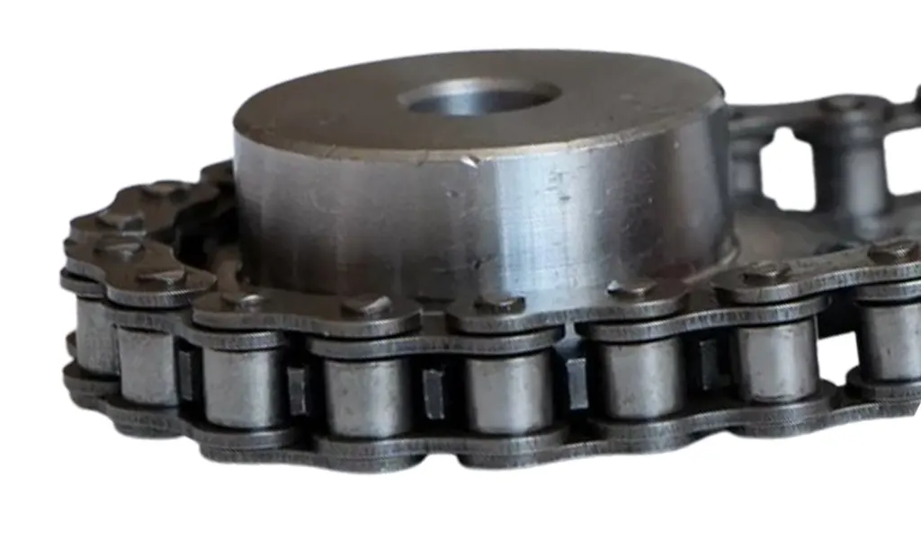
Choose a practical small-sprocket tooth count first
Base the decision on select a small sprocket supported by the chain manufacturer rating table and acceptable for the desired smoothness. It matters because more teeth generally reduce articulation angle and polygonal speed variation while increasing sprocket diameter. During service, very small tooth counts save space but intensify engagement dynamics. A poor assumption can cause minimizing sprocket diameter without considering chain dynamics can increase noise, vibration, and wear.
Use this confirmation: compare several tooth counts in the supplier rating table and calculate their pitch diameters. Proceed when you can choose the smallest tooth count that satisfies rating, dynamics, and packaging together. If readings vary around the chain or sprocket, retain the spread instead of hiding it in one average.
Calculate the matching large sprocket
The controlling action is to multiply or divide the chosen small-sprocket teeth by the required ratio as appropriate and round only to an integer tooth count that produces an acceptable actual ratio. Its significance comes from sprockets require whole teeth, so most real drives have a small ratio deviation from the theoretical target. In the field, a one-tooth change on a small sprocket has a larger percentage effect than on a large sprocket. The failure consequence is rounding without recalculating output speed can create an unacceptable process error.
Check the hardware directly: calculate actual ratio and driven RPM for the nearest viable large-sprocket tooth counts. Approval requires that you can accept a pair only when the resulting speed lies within the process tolerance. Write down any uncertainty that still needs a drawing, manual, or supplier response.
Check sprocket diameters and shaft interfaces
First, calculate or obtain pitch and outside diameters plus bore, hub, keyway, and face width for both sprockets. That step is tied to the mathematically correct tooth pair may not fit guards, shafts, bearings, or adjacent equipment. A practical observation is that large ratios can produce a driven sprocket that dominates the machine envelope. Missing it can lead to selecting ratio before checking diameter can force a late redesign.
For evidence, overlay the sprocket drawings on the machine layout and verify shaft bore and hub constraints. Finish when you can confirm both sprockets fit with guard, chain, and service clearance. Retain enough context to distinguish a new-chain dimension from a wear-affected measurement.
Recalculate center distance and chain length
Treat calculate link count for the selected tooth pair and check wrap and take-up position as the control point. The reason is changing tooth counts changes chain length and the geometry of the slack span. Real installations also show that a ratio correction can move the take-up out of range or reduce useful wrap on the small sprocket. The likely consequence of error is treating tooth count as independent from chain length creates installation surprises.
Make the check at the machine: calculate theoretical pitches for the actual shaft centers and compare practical link counts. The release criterion is to verify the selected pair can be assembled with suitable slack and adjustment travel. Record whether the drive was stopped, loaded, warm, cold, clean, or contaminated as relevant.
Review the dynamic operating point
Do not choose the hardware until you use actual chain speed, load fluctuation, and sprocket tooth counts to check vibration and lubrication requirements. This matters because the ratio calculation only establishes average speed; it does not confirm drive smoothness or chain rating. Remember that high speed and fluctuating load can excite the chain span or machine structure. If ignored, a correct ratio can still be a poor mechanical design.
Validate with a repeatable observation: run a controlled trial and observe noise, vibration, chain tracking, and sprocket entry. Move on after you can revise tooth count, pitch, tensioning, or guidance if the drive shows unacceptable dynamic behavior. Preserve the source of any numerical limit that belongs to a specific chain series.
Calculation and validation table
| 决策点 | 检查或计算 | 接受证据 |
|---|---|---|
| Define the required shaft-speed ratio | record maximum and normal input RPM plus the required output RPM at the same operating mode | confirm the ratio represents the actual process requirement rather than a rounded nominal value |
| Choose a practical small-sprocket tooth count first | compare several tooth counts in the supplier rating table and calculate their pitch diameters | choose the smallest tooth count that satisfies rating, dynamics, and packaging together |
| Calculate the matching large sprocket | calculate actual ratio and driven RPM for the nearest viable large-sprocket tooth counts | accept a pair only when the resulting speed lies within the process tolerance |
| Check sprocket diameters and shaft interfaces | overlay the sprocket drawings on the machine layout and verify shaft bore and hub constraints | confirm both sprockets fit with guard, chain, and service clearance |
| Recalculate center distance and chain length | calculate theoretical pitches for the actual shaft centers and compare practical link counts | verify the selected pair can be assembled with suitable slack and adjustment travel |
| Review the dynamic operating point | run a controlled trial and observe noise, vibration, chain tracking, and sprocket entry | revise tooth count, pitch, tensioning, or guidance if the drive shows unacceptable dynamic behavior |
| For this article, do not close the job until the speed ratio evidence and every critical mating interface are recorded together. | ||
有些看似连锁问题的故障实际上是由相邻硬件控制的。 review industrial sprocket tooth-count options helps illustrate that broader sprocket tooth-count selection context, while the acceptance criteria still come from the actual chain, sprocket, tensioning arrangement, and OEM documentation.
Calculation mistakes that distort selection
Release check: confirm the ratio represents the actual process requirement rather than a rounded nominal value.
Release check: choose the smallest tooth count that satisfies rating, dynamics, and packaging together.
Release check: accept a pair only when the resulting speed lies within the process tolerance.
Release check: confirm both sprockets fit with guard, chain, and service clearance.
Calculation FAQs
Release the result only after a physical cross-check
Release the work only when the record connects speed ratio and driving sprocket to the physical condition verified in “Review the dynamic operating point.” Include photos or measurements where they clarify the interface, and reference the document that owns any exact limit. The 工业链传动解决方案 然后可以利用它在不失去原有工程基础的情况下探索替代方案。
Do not hide a remaining assumption inside the purchase description. send the application data to the chain engineering team with the machine duty, measured interfaces, photographs, and the unresolved question around driven sprocket. A clear uncertainty is actionable; an undocumented guess becomes a future troubleshooting problem.
Send the operating condition, speed ratio, driving sprocket, layout evidence, and the unresolved interface so the next decision is based on machine data rather than assumption.