Define inputs before using the equation
Treat this task as an engineering verification sequence. Each step should either produce a number, a physical observation, or a documented acceptance condition. Chain speed is the bridge between shaft rotation and the linear motion of the chain. It is simple to calculate, but only useful when the pitch units and sprocket speed are defined correctly and the result is then checked against the chain supplier rating and lubrication method.
Use the transmission chain product range as a map of available chain families only after you have captured chain speed and chain pitch. For this topic, the first release condition is specific: confirm the RPM is the maximum or design operating value relevant to the duty. That sequence keeps catalog browsing from turning into a pitch-only or appearance-only substitution.
- Chain Speed
- Check this point at the machine and document any uncertainty that still requires a supplier drawing or manual.
- Chain Pitch
- Record this requirement with enough context that a second engineer can reproduce the same selection or diagnosis.
- Sprocket Teeth
- Capture this input from a drawing, measurement, calculation, or operating record before the decision advances.
- Shaft Rpm
- Treat this as a controlled variable; note its value, unit, operating state, and source in the job record.
- M/Min
- Verify this item against the physical drive and the current supplier data instead of estimating it from appearance.
Choose the correct rotating sprocket
First, use the tooth count and RPM of the sprocket whose shaft speed is known and keep the speed from the same operating condition as the load calculation. That step is tied to chain speed is set by how many pitches the sprocket advances per revolution. A practical observation is that using motor RPM when a reducer sits between the motor and sprocket can inflate chain speed by the reduction ratio. Missing it can lead to an incorrect speed can place the selection in the wrong rating or lubrication region.
For evidence, trace the power path from motor through reducer to the driving sprocket and record the actual sprocket-shaft RPM. Finish when you can confirm the RPM is the maximum or design operating value relevant to the duty. Retain enough context to distinguish a new-chain dimension from a wear-affected measurement.
Express pitch and units explicitly
Treat convert chain pitch to millimeters for the m/min form of the equation or to meters for a direct SI calculation as the control point. The reason is unit consistency is what turns a correct equation into a correct number. Real installations also show that a pitch written as 19.05 can mean millimeters while the speed formula may expect meters. The likely consequence of error is mixing millimeters and meters creates a thousand-fold error that can pass unnoticed in a spreadsheet.
Make the check at the machine: write the unit next to every input before calculation and include the chain designation as a cross-check. The release criterion is to verify the pitch matches the chain drawing and the numerical result has a plausible order of magnitude. Record whether the drive was stopped, loaded, warm, cold, clean, or contaminated as relevant.
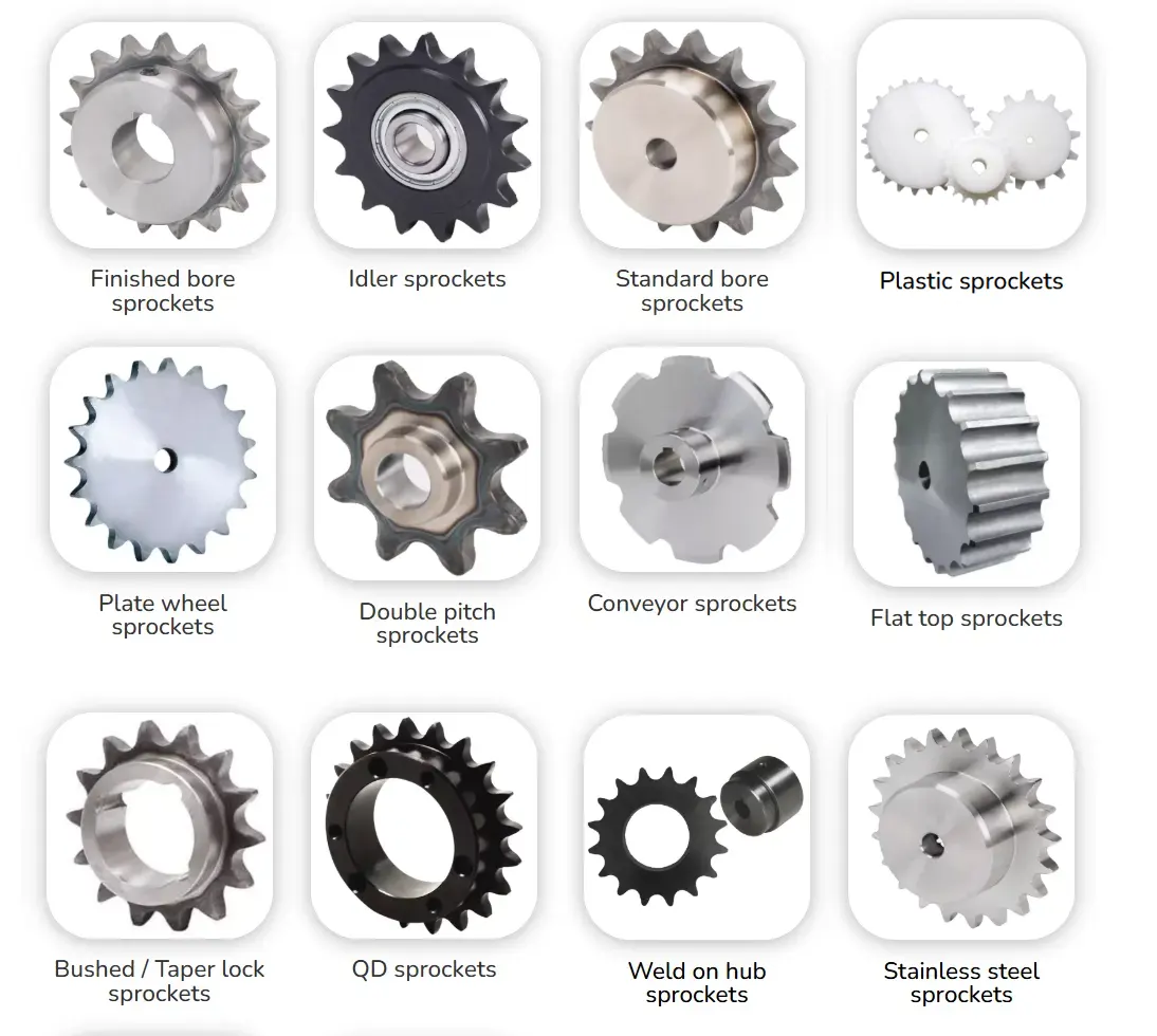
Apply the pitch-teeth-RPM relationship
Do not choose the hardware until you multiply pitch by sprocket teeth and revolutions per minute, then convert the traveled length into the desired speed unit. This matters because one sprocket revolution advances the chain by approximately one pitch for each tooth engaged around the pitch circle. Remember that the equation represents nominal linear chain travel and does not describe instantaneous chordal speed fluctuation. If ignored, treating nominal chain speed as perfectly constant can hide vibration issues in small-tooth high-speed drives.
Validate with a repeatable observation: calculate with a documented equation and retain the unrounded intermediate value for later force calculations. Move on after you can recalculate independently or with a second unit system when the result will drive a critical selection. Preserve the source of any numerical limit that belongs to a specific chain series.
Use speed to calculate nominal chain pull
A reliable result starts when you combine transmitted power with chain speed when a force estimate is needed for engineering checks. The underlying reason is for the same transmitted power, lower chain speed corresponds to higher tangential chain force. In service, chain pull is a useful load indicator but does not replace fatigue-based rating tables or shock factors. An incorrect input may create selecting a chain solely because its tensile strength exceeds the calculated pull ignores fatigue and service conditions.
Use the following field evidence: use the actual transmitted power and the same chain speed operating point in the force equation. Accept the result only if you can compare the resulting force with supplier allowable-load guidance and the applicable service-factor method. If the check is visual, add a dimension or operating observation whenever practical.
Connect speed to lubrication and wear control
Establish the condition by choosing to use chain speed together with chain size and load to select the lubrication method from the manufacturer guidance. It affects the drive because joint articulation frequency rises as the chain circulates faster and adequate oil delivery becomes more demanding. A useful constraint is that manual oiling that works on a slow intermittent drive may be inadequate on a faster enclosed drive. Getting it wrong can produce insufficient lubrication at speed accelerates pin-bushing wear, heat, noise, and elongation.
Confirm the condition this way: inspect the guard, oil path, and joint wetting during operation or a controlled trial. The step passes when you can confirm the chosen lubrication method covers the calculated speed and operating environment. Keep the evidence beside the chain designation and machine location in the maintenance record.
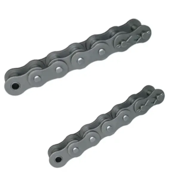
Check dynamics rather than speed alone
Begin with the physical requirement: review small-sprocket tooth count, span length, load fluctuation, and vibration after calculating nominal speed. It is connected to polygonal action and engagement impact depend on geometry as well as linear chain speed. At site level, two drives with equal chain speed can behave differently if one uses a much smaller sprocket. The avoidable outcome is ignoring tooth count can leave a noisy or vibrating drive even when nominal speed is within rating.
Inspect as follows: observe the slack span and sprocket entry during a trial run and check for periodic vibration or impact. Release the step after you can increase tooth count, revise pitch, improve guidance, or change layout if the dynamic behavior is unacceptable. Repeat the check after adjustment whenever the adjustment itself can change the measured condition.
Calculation and validation table
| Decision point | Inspection or calculation | Acceptance evidence |
|---|---|---|
| Choose the correct rotating sprocket | trace the power path from motor through reducer to the driving sprocket and record the actual sprocket-shaft RPM | confirm the RPM is the maximum or design operating value relevant to the duty |
| Express pitch and units explicitly | write the unit next to every input before calculation and include the chain designation as a cross-check | verify the pitch matches the chain drawing and the numerical result has a plausible order of magnitude |
| Apply the pitch-teeth-RPM relationship | calculate with a documented equation and retain the unrounded intermediate value for later force calculations | recalculate independently or with a second unit system when the result will drive a critical selection |
| Use speed to calculate nominal chain pull | use the actual transmitted power and the same chain speed operating point in the force equation | compare the resulting force with supplier allowable-load guidance and the applicable service-factor method |
| Connect speed to lubrication and wear control | inspect the guard, oil path, and joint wetting during operation or a controlled trial | confirm the chosen lubrication method covers the calculated speed and operating environment |
| Check dynamics rather than speed alone | observe the slack span and sprocket entry during a trial run and check for periodic vibration or impact | increase tooth count, revise pitch, improve guidance, or change layout if the dynamic behavior is unacceptable |
| For this article, do not close the job until the chain speed evidence and every critical mating interface are recorded together. | ||
The neighboring component matters because chain behavior depends on the complete drive. review small-pitch roller-chain sizing context provides additional product context for chain speed calculation; use it to frame questions, then confirm dimensions and ratings from the exact component drawing used on the machine.
Calculation mistakes that distort selection
Release check: confirm the RPM is the maximum or design operating value relevant to the duty.
Release check: verify the pitch matches the chain drawing and the numerical result has a plausible order of magnitude.
Release check: recalculate independently or with a second unit system when the result will drive a critical selection.
Release check: compare the resulting force with supplier allowable-load guidance and the applicable service-factor method.
Calculation FAQs
Release the result only after a physical cross-check
Close this calculation task with a traceable record of chain speed, chain pitch, and the inspection result for “Check dynamics rather than speed alone.” The release note should state the operating condition used for the check and identify the drawing, rating table, or machine document that set any model-specific limit. The chain-and-sprocket drive options can provide broader chain-drive context when a neighboring component also needs review.
If chain speed calculation still contains an unresolved variable, send the application data to the chain engineering team with the operating state, the relevant measurements, photographs of the chain and sprockets, and the unknown item clearly marked. For this topic, pay particular attention to sprocket teeth. Resolving that gap before purchase or restart is usually cheaper than diagnosing a second problem created by an assumed value.
Send the operating condition, chain speed, chain pitch, layout evidence, and the unresolved interface so the next decision is based on machine data rather than assumption.